8.6 Alternator
Fragment manuala — str. 390–394

📋 Tekst do skopiowania (OCR/wyszukiwanie)
ALTERNATOR 8.6
PREPARE
1. Remove main fuse. POWER DISCONNECT (Page 8-4).
2. Remove coolant manifold. COOLANT MANIFOLD
(Page 4-51 ).
REMOVE
PART NUMBER TOOL NAME
HD-52968 ROTOR LOCKING TOOL
HD-52969 ROTOR SHELL REMOVAL PIN
Rotor
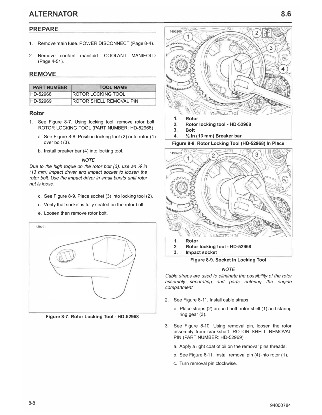
1. Rotor
1. See Figure 8-7. Using locking tool, remove rotor bolt. 2. Rotor locking tool - HD-52968
ROTOR LOCKING TOOL (PART NUMBER: HD-52968) 3. Bolt
a. See Figure 8-8. Position locking tool (2) onto rotor (1) 4. ½ in (13 mm) Breaker bar
over bolt (3). Figure 8-8. Rotor Locking Tool (HD-52968) In Place
b. Install breaker bar (4) into locking tool.
NOTE
Due to the high toque on the rotor bolt (3), use an ½ in
(13 mm) impact driver and impact socket to loosen the
rotor bolt. Use the impact driver in small bursts until rotor
nut is loose.
c. See Figure 8-9. Place socket (3) into locking tool (2).
d. Verify that socket is fully seated on the rotor bolt.
e. Loosen then remove rotor bolt.
1429791
1. Rotor
2. Rotor locking tool - HD-52968
3. Impact socket
Figure 8-9. Socket in Locking Tool
NOTE
Cable straps are used to eliminate the possibility of the rotor
assembly separating and parts entering the engine
compartment.
2. See Figure 8-11. Install cable straps
a. Place straps (2) around both rotor shell (1) and staring
Figure 8-7. Rotor Locking Tool - HD-52968 ring gear (3).
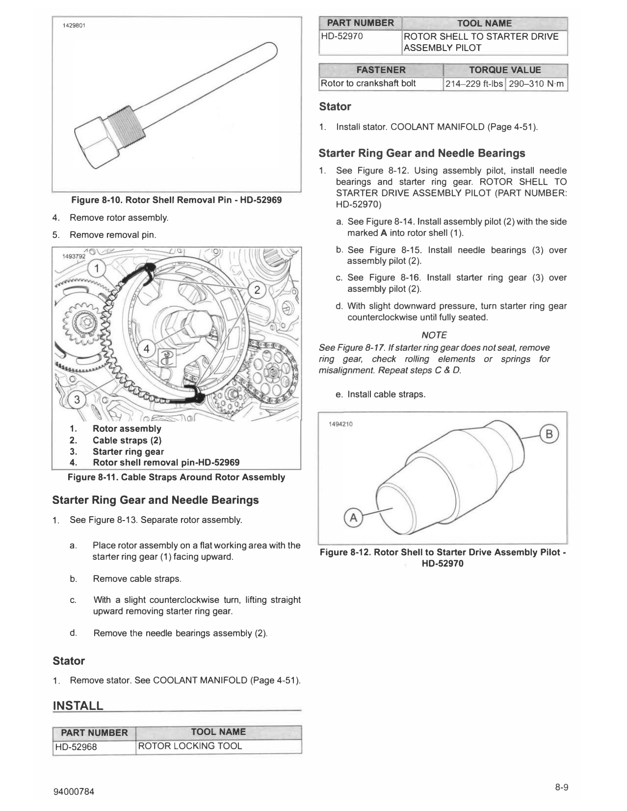
3. See Figure 8-10. Using removal pin, loosen the rotor
assembly from crankshaft. ROTOR SHELL REMOVAL
PIN (PART NUMBER: HD-52969)
a. Apply a light coat of oil on the removal pins threads.
b. See Figure 8-11. Install removal pin (4) into rotor (1).
c. Turn removal pin clockwise.
1429801 PART NUMBER TOOL NAME
HD-52970 ROTOR SHELL TO STARTER DRIVE
ASSEMBLY PILOT
FASTENER TORQUE VALUE
Rotor to crankshaft bolt 214-229 ft-lbs 290-310 N·m
Stator
1. Install stator. COOLANT MANIFOLD (Page 4-51).
Starter Ring Gear and Needle Bearings
1. See Figure 8-12. Using assembly pilot, install needle
bearings and starter ring gear. ROTOR SHELL TO
STARTER DRIVE ASSEMBLY PILOT (PART NUMBER:
Figure 8-10. Rotor Shell Removal Pin - HD-52969 HD-52970)
4. Remove rotor assembly. a. See Figure 8-14. Install assembly pilot (2) with the side
5. Remove removal pin. marked A into rotor shell (1).
b. See Figure 8-15. Install needle bearings (3) over
assembly pilot (2).
c. See Figure 8-16. Install starter ring gear (3) over
assembly pilot (2).
d. With slight downward pressure, turn starter ring gear
counterclockwise until fully seated.
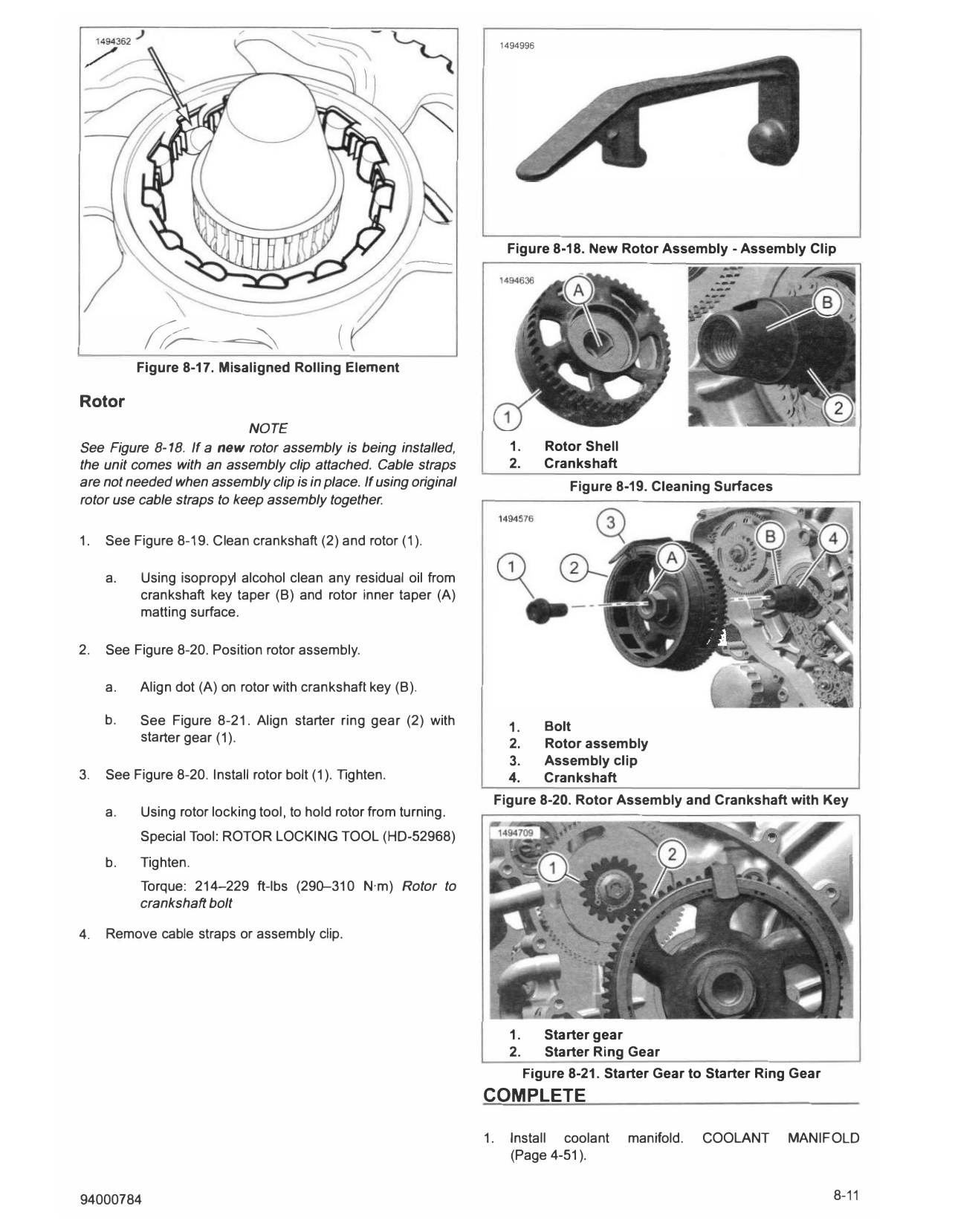
NOTE
See Figure 8-17. If starter ring gear does not seat, remove
ring gear, check rolling elements or springs for
misalignment. Repeat steps C & D.
e. Install cable straps.
1. Rotor assembly
2. Cable straps (2)
3. Starter ring gear
4. Rotor shell removal pin-HD-52969
Figure 8-11. Cable Straps Around Rotor Assembly
Starter Ring Gear and Needle Bearings
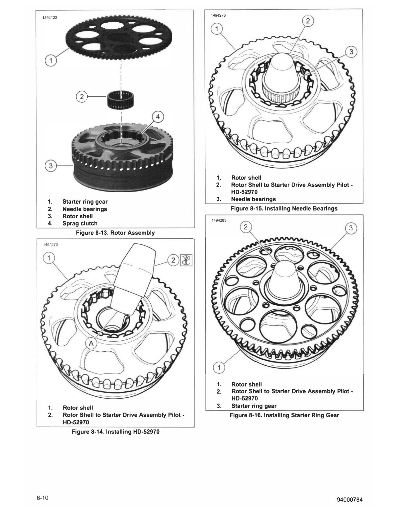
1. See Figure 8-13. Separate rotor assembly.
a. Place rotor assembly on a flat working area with the
starter ring gear (1) facing upward. Figure 8-12. Rotor Shell to Starter Drive Assembly Pilot -
HD-52970
b. Remove cable straps.
c. With a slight counterclockwise turn, lifting straight
upward removing starter ring gear.
d. Remove the needle bearings assembly (2).
Stator
1. Remove stator. See COOLANT MANIFOLD (Page 4-51).
INSTALL
PART NUMBER TOOLNAME
HD-52968 ROTOR LOCKING TOOL
94000784 8-9
0----
1. Rotor shell
2. Rotor Shell to Starter Drive Assembly Pilot -
HD-52970
1. Starter ring gear 3. Needle bearings
2. Needle bearings Figure 8-15. Installing Needle Bearings
3. Rotor shell
1494283
4. Sprag clutch
2 3
Figure 8-13. Rotor Assembly
1. Rotor shell
2. Rotor Shell to Starter Drive Assembly Pilot -
HD-52970
1. Rotor shell 3. Starter ring gear
2. Rotor Shell to Starter Drive Assembly Pilot - Figure 8-16. Installing Starter Ring Gear
HD-52970
Figure 8-14. Installing HD-52970
8-10 94000784
1494996
Figure 8-18. New Rotor Assembly - Assembly Clip
� (
Figure 8-17. Misaligned Rolling Element
Rotor
NOTE
See Figure 8-18. If a new rotor assembly is being installed, 1. Rotor Shell
the unit comes with an assembly clip attached. Cable straps 2. Crankshaft
are not needed when assembly clip is in place. If using original Figure 8-19. Cleaning Surfaces
rotor use cable straps to keep assembly together.
1. See Figure 8-19. C lean crankshaft (2) and rotor (1).
a. Using isopropyl alcohol clean any residual oil from
crankshaft key taper (8) and rotor inner taper (A)
matting surface.
2. See Figure 8-20. Position rotor assembly.
a. Align dot (A) on rotor with crankshaft key (8).
b. See Figure 8-21. Align starter ring gear (2) with Bolt
1.
starter gear (1). 2. Rotor assembly
3. Assembly clip
3. See Figure 8-20. Install rotor bolt (1). Tighten. 4. Crankshaft
Figure 8-20. Rotor Assembly and Crankshaft with Key
a. Using rotor locking tool, to hold rotor from turning.
Special Tool: ROTOR LOCKING TOOL (HD-52968)
b. Tighten.
Torque: 214-229 ft-lbs (290-310 N·m) Rotor to
crankshaft bolt
4. Remove cable straps or assembly clip.
1. Starter gear
2. Starter Ring Gear
Figure 8-21. Starter Gear to Starter Ring Gear
COMPLETE
1. Install coolant manifold. COOLANT MANIFOLD
(Page 4-51).
94000784 8-11
2. Install main fuse. POWER DISCONNECT (Page 8-4).
8-12 94000784