8.45 Engine Wire Harness
Fragment manuala — str. 448–451
📋 Tekst do skopiowania (OCR/wyszukiwanie)
ENGINE WIRE HARNESS 8.45
PREPARE f. Front exhaust cam sensor (17).
g. Rear exhaust VVT phaser (3).
1. Remove fairing. See FAIRING (Page 3-89).
h. Rear intake VVT phaser (5).
2. Remove seat. See SEAT (Page 3-113).
i. Front intake VVT phaser (13).
3. Purge fuel system. See PURGE FUEL LINE (Page 6-9).
j. Front exhaust VVT phaser (16).
4. Remove main fuse. See POWER DISCONNECT
k. Rear ignition coil (single) (4).
(Page 8-4).
I. Front ignition coil (single) (14).
5. Remove fuel tank. See FUEL TANK (Page 6-13).
m. Post catalyst HO2S (International models) (1).
6. Remove skid plate. See SKID PLATE (Page 3-92).
n. ECM (10).
7. Remove engine guards. See ENGINE GUARDS
(Page 3-94). 0. Sensor jumper harness (8).
8. Remove fairing lowers. See FAIRING LOWERS 6. See Figure 8-97. Disconnect connectors:
(Page 3-90).
a. Right hand controls (5).
9. Relocate radiator. Do not disconnect hoses. See
RADIATOR (Page 7-18). b. Ambient air temperature sensor (6).
c. Right front turn signal (4).
10. Remove output sprocket cover. See CHAIN GUARDS
(Page 3-76).
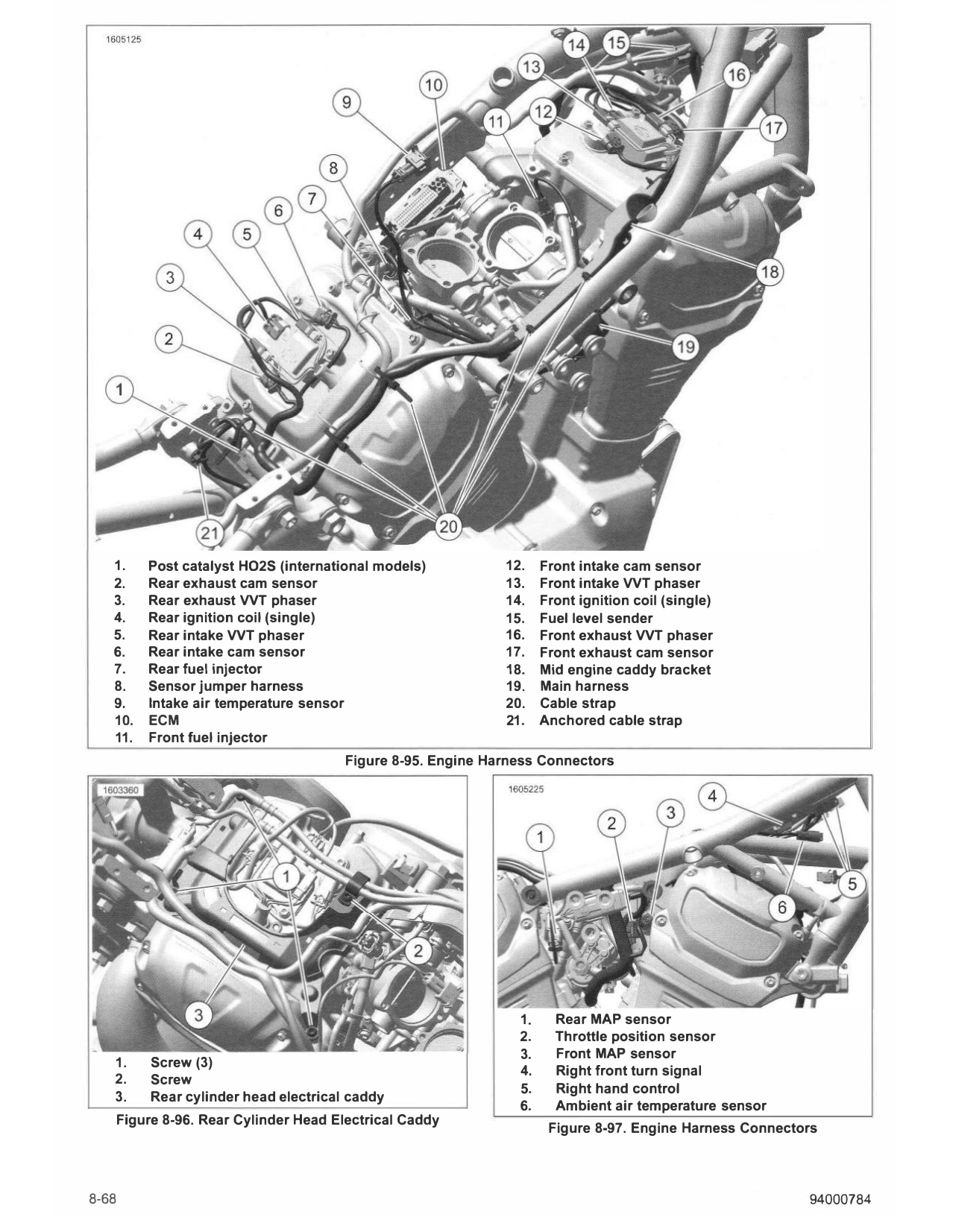
7. See Figure 8-98. Cut and discard cable straps (1) and
anchored cable straps (8).
11. Remove air box assembly. See AIR BOX (Page 6-3).
8. Pull radiator forward as far as hoses allow.
12. Remove side mount ignition coil and bracket. See
IGNITION COIL (Page 8-16).
9. Disconnect connectors:
13. Remove induction module. See INDUCTION MODULE
a. Front HO2S (2).
(Page 6-28).
b. Rear HO2S (3).
14. Cover cylinder head intake ports with shop towels.
C. Jiffy stand sensor (4).
REMOVE
d. Cooling fan (5).
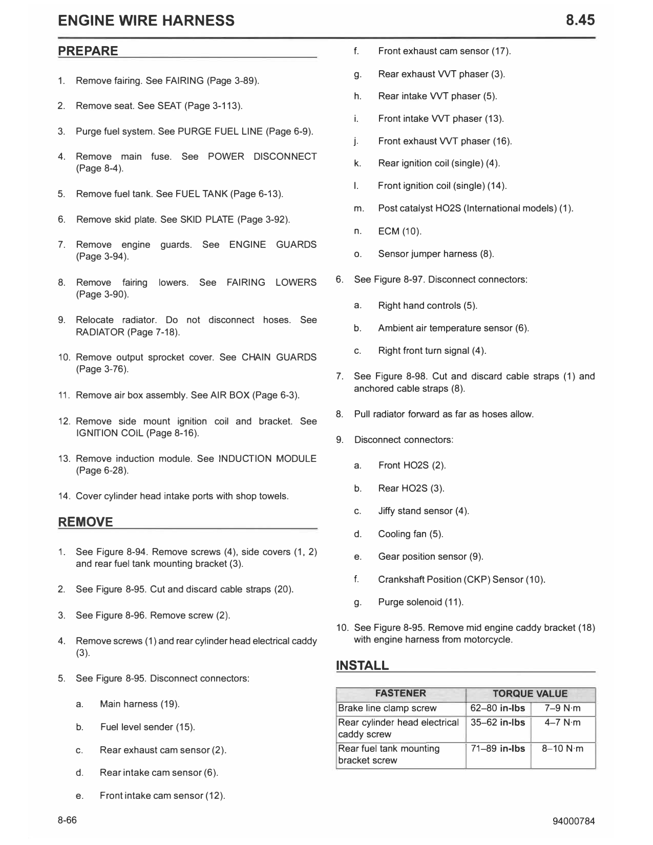
1. See Figure 8-94. Remove screws (4), side covers (1, 2) e. Gear position sensor (9).
and rear fuel tank mounting bracket (3).
f. Crankshaft Position (CKP) Sensor (10).
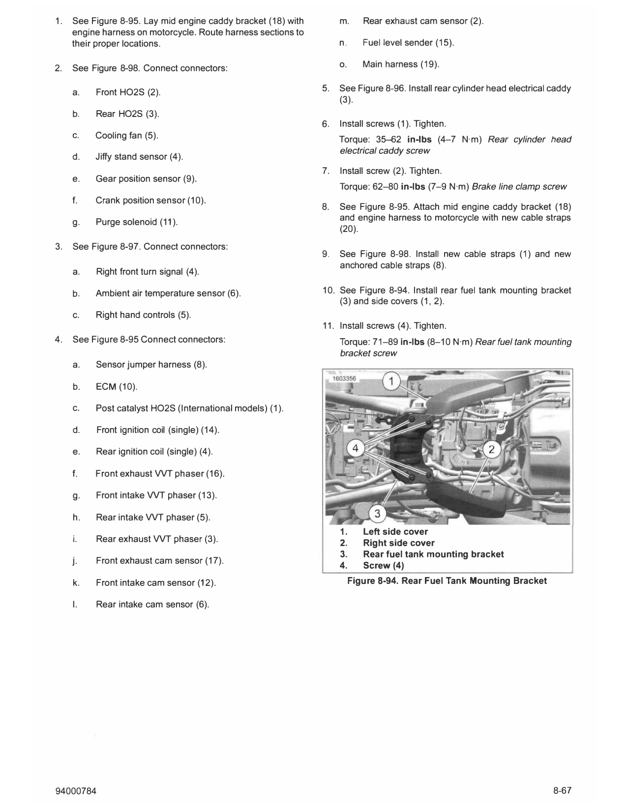
2. See Figure 8-95. Cut and discard cable straps (20).
g. Purge solenoid (11).
3. See Figure 8-96. Remove screw (2).
10. See Figure 8-95. Remove mid engine caddy bracket (18)
4. Remove screws (1) and rear cylinder head electrical caddy with engine harness from motorcycle.
(3).
INSTALL
5. See Figure 8-95. Disconnect connectors:
FASTENER TORQUE VALUE
a. Main harness (19). Brake line clamp screw 62-80 in-lbs 7-9 N·m
b. Fuel level sender (15).
Rear cylinder head electrical 35-62 in-lbs 4-7 N·m
caddy screw
c. Rear exhaust cam sensor (2). Rear fuel tank mounting 71-89 in-lbs 8-10 N·m
bracket screw
d. Rear intake cam sensor (6).
e. Front intake cam sensor (12).
8-66 94000784
1. See Figure 8-95. Lay mid engine caddy bracket (18) with m. Rear exhaust cam sensor (2).
engine harness on motorcycle. Route harness sections to
their proper locations. n. Fuel level sender (15).
2. See Figure 8-98. Connect connectors: o. Main harness (19).
a. Front HO2S (2). 5. See Figure 8-96. Install rear cylinder head electrical caddy
(3).
b. Rear HO2S (3).
6. Install screws (1). Tighten.
C. Cooling fan (5). Torque: 35--62 in-lbs (4-7 N·m) Rear cylinder head
electrical caddy screw
d. Jiffy stand sensor (4).
7. Install screw (2). Tighten.
e. Gear position sensor (9).
Torque: 62-80 in-lbs (7-9 N·m) Brake line clamp screw
f. Crank position sensor (10).
8. See Figure 8-95. Attach mid engine caddy bracket (18)
g. Purge solenoid (11). and engine harness to motorcycle with new cable straps
(20).
3. See Figure 8-97. Connect connectors:
9. See Figure 8-98. Install new cable straps (1) and new
anchored cable straps (8).
a. Right front turn signal (4).
b. Ambient air temperature sensor (6). 10. See Figure 8-94. Install rear fuel tank mounting bracket
(3) and side covers (1, 2).
c. Right hand controls (5).
11. Install screws (4). Tighten.
4. See Figure 8-95 Connect connectors: Torque: 71-89 in-lbs (8-10 N·m) Rearfuel tank mounting
bracket screw
a. Sensor jumper harness (8).
b. ECM (10).
c. Post catalyst HO2S (International models) (1).
d. Front ignition coil (single) (14).
e. Rear ignition coil (single) (4).
f. Front exhaust VVT phaser (16).
g. Front intake VVT phaser (13).
h. Rear intake VVT phaser (5).
1. Left side cover
i. Rear exhaust VVT phaser (3). 2. Right side cover
3. Rear fuel tank mounting bracket
j. Front exhaust cam sensor (17).
4. Screw (4)
k. Front intake cam sensor (12). Figure 8-94. Rear Fuel Tank Mounting Bracket
I. Rear intake cam sensor (6).
94000784 8-67
1. Post catalyst HO2S (international models) 12. Front intake cam sensor
2. Rear exhaust cam sensor 13. Front intake VVT phaser
3. Rear exhaust VVT phaser 14. Front ignition coil (single)
4. Rear ignition coil (single) 15. Fuel level sender
5. Rear intake VVT phaser 16. Front exhaust VVT phaser
6. Rear intake cam sensor 17. Front exhaust cam sensor
7. Rear fuel injector 18. Mid engine caddy bracket
8. Sensor jumper harness 19. Main harness
9. Intake air temperature sensor 20. Cable strap
10. ECM 21. Anchored cable strap
11. Frontfuel injector
Figure 8-95. Engine Harness Connectors
1. Rear MAP sensor
2. Throttle position sensor
3. Front MAP sensor
1. Screw (3)
4. Right front turn signal
2. Screw
5. Right hand control
3. Rear cylinder head electrical caddy
6. Ambient air temperature sensor
Figure 8-96. Rear Cylinder Head Electrical Caddy
Figure 8-97. Engine Harness Connectors
8-68 94000784
@-_____
1. Cable strap 7. Throttle motor
2. Front H02S 8. Anchored cable strap
3. Rear H02S 9. Gear position sensor
4. Jiffy stand sensor 10. Crank position sensor
5. Cooling fan 11. Purge solenoid
6. Side mount ignition coil
Figure 8-98. Engine Harness Connectors
COMPLETE 6. Install radiator. See RADIATOR (Page 7-18).
1. Remove shop towels from cylinder head intake ports. 7. Install fairing lowers. See FAIRING LOWERS (Page 3-90).
2. Install induction module. See INDUC TION MODULE 8. Install engine guards. See ENGINE GUARDS (Page 3-94).
(Page 6-28).
9. Install skid plate. See SKID PLATE (Page 3-92).
3. Install side mount ignition coil and bracket. See IGNITION
COIL (Page 8-16). 10. Install fuel tank. See FUEL TANK (Page 6-13).
4. Install air box assembly. See AIR BOX (Page 6-3). 11. Install main fuse. See POWER DISCONNECT
(Page 8-4).
5. Install output sprocket cover. See CHAIN GUARDS
(Page 3-76). 12. Install seat. See SEAT (Page 3-113).
13. Install fairing. See FAIRING (Page 3-89).
94000784 8-69