8.44 Variable Valve Timing (Vvt) Harness
Fragment manuala — str. 446–447
📋 Tekst do skopiowania (OCR/wyszukiwanie)
VARIABLE VALVE TIMING (WT) HARNESS 8.44
PREPARE 3. Grasp upper harness grommet and gently pull until it pops
into place in cover.
1. Remove seat. See SEAT (Page 3-113). NOTE
• Do not pull on WT harness wires or connectors when
2. Purge fuel system. See PURGE FUEL LINE (Page 6-9). installing the WT harness.
• See Figure 8-92. Make sure grommet's sealing ring (2)
3. Remove main fuse. See POWER DISCONNECT is not visible.
(Page 8-4).
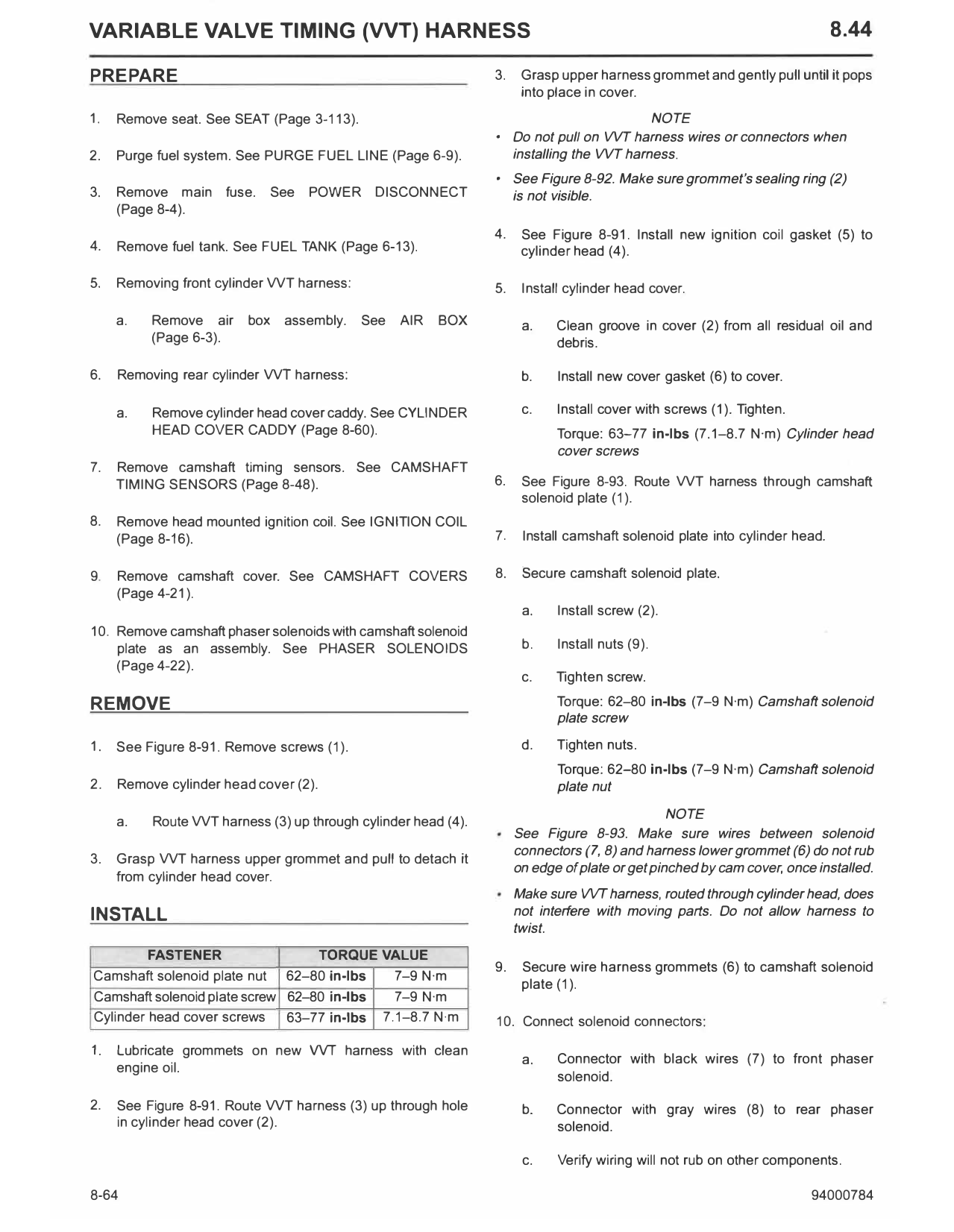
4. See Figure 8-91. Install new ignition coil gasket (5) to
4. Remove fuel tank. See FUEL TANK (Page 6-13). cylinder head (4).
5. Removing front cylinder WT harness: 5. Install cylinder head cover.
a. Remove air box assembly. See AIR BOX a. Clean groove in cover (2) from all residual oil and
(Page 6-3). debris.
6. Removing rear cylinder WT harness: b. Install new cover gasket (6) to cover.
a. Remove cylinder head cover caddy. See CYLINDER c. Install cover with screws (1). Tighten.
HEAD COVER CADDY (Page 8-60). Torque: 63-77 in-lbs (7.1-8.7 N·m) Cylinder head
cover screws
7. Remove camshaft timing sensors. See CAMSHAFT
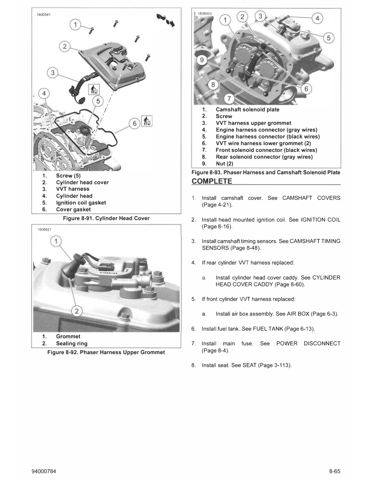
TIMING SENSORS (Page 8-48). 6. See Figure 8-93. Route WT harness through camshaft
solenoid plate (1).
8. Remove head mounted ignition coil. See IGNITION COIL
(Page 8-16). 7. Install camshaft solenoid plate into cylinder head.
9. Remove camshaft cover. See CAMSHAFT COVERS 8. Secure camshaft solenoid plate.
(Page 4-21).
a. Install screw (2).
10. Remove camshaft phaser solenoids with camshaft solenoid
plate as an assembly. See PHASER SOLENOIDS b. Install nuts (9).
(Page 4-22).
c. Tighten screw.
REMOVE Torque: 62-80 in-lbs (7-9 N·m) Camshaft solenoid
plate screw
1. See Figure 8-91. Remove screws (1). d. Tighten nuts.
Torque: 62-80 in-lbs (7-9 N·m) Camshaft solenoid
2. Remove cylinder head cover (2). plate nut
NOTE
a. Route WT harness (3) up through cylinder head (4).
See Figure 8-93. Make sure wires between solenoid
connectors (7, 8) and harness lower grommet (6) do not rub
3. Grasp WT harness upper grommet and pull to detach it
on edge ofplate or get pinched by cam cover, once installed.
from cylinder head cover.
Make sure WT harness, routed through cylinder head, does
INSTALL not interfere with moving parts. Do not allow harness to
twist.
FASTENER TORQUE VALUE
9. Secure wire harness grommets (6) to camshaft solenoid
Camshaft solenoid plate nut 62-80 in-lbs 7-9 N·m
plate (1).
Camshaft solenoid plate screw 62-80 in-lbs 7-9 N·m
Cylinder head cover screws 63-77 in-lbs 7.1-8.7 N·m 10. Connect solenoid connectors:
1. Lubricate grommets on new WT harness with clean
a. Connector with black wires (7) to front phaser
engine oil.
solenoid.
2. See Figure 8-91. Route WT harness (3) up through hole b. Connector with gray wires (8) to rear phaser
in cylinder head cover (2). solenoid.
c. Verify wiring will not rub on other components.
8-64 94000784
1400541
1. Camshaft solenoid plate
2. Screw
3. WT harness upper grommet
4. Engine harness connector (gray wires)
5. Engine harness connector (black wires)
6. WT wire harness lower grommet (2)
7. Front solenoid connector (black wires)
8. Rear solenoid connector (gray wires)
9. Nut(2)
Figure 8-93. Phaser Harness and Camshaft Solenoid Plate
1. Screw (5)
2. Cylinder head cover COMPLETE
3. VVT harness
4. Cylinder head 1. Install camshaft cover. See CAMSHAFT COVERS
5. Ignition coil gasket (Page 4-21).
6. Cover gasket
Figure 8-91. Cylinder Head Cover 2. Install head mounted ignition coil. See IGNITION COIL
1606821
(Page 8-16).
3. Install camshaft timing sensors. See CAMSHAFT TIMING
SENSORS (Page 8-48).
4. If rear cylinder VVT harness replaced:
a. Install cylinder head cover caddy. See CYLINDER
HEAD COVER CADDY (Page 8-60).
5. If front cylinder WT harness replaced:
a. Install air box assembly. See AIR BOX (Page 6-3).
6. Install fuel tank. See FUEL TANK (Page 6-13).
1. Grommet
2. Sealing ring 7. Install main fuse. See POWER DISCONNECT
Figure 8-92. Phaser Harness Upper Grommet (Page 8-4).
8. Install seat. See SEAT (Page 3-113).
94000784 8-65