8.46 Main Wire Harness
Fragment manuala — str. 452–456
📋 Tekst do skopiowania (OCR/wyszukiwanie)
MAIN WIRE HARNESS 8.46
PREPARE 5. Disconnect IM (2), headlamp (13) and bank lamp (14)
connectors.
1. Purge fuel system. See PURGE FUEL LINE(Page 6-9).
6. Disconnect horn connectors(11, 12).
2. Remove right side steering head cover. See SIDE
COVERS(Page 3-52). 7. Remove the MT sensor(4) and main fuse(6) from the
RH electrical caddy.
3. Remove main fuse. See POWER DISCONNECT
(Page 8-4). 8. Disconnect LH electrical caddy connectors.
4. Remove seat. See SEAT (Page 3-113). a. LH control(5).
b. Front left turn(7).
5. Remove fuel tank. See FUEL T ANK(Page 6-13).
C. Stroke(8).
6. Remove air box. See AIR BOX(Page 6-3).
d. Damping(9).
7. Remove seat base assembly. See T AIL SECTION
(Page 3-114). e. Fuel level sender(10).
REMOVE 9. See Figure 8-101. Discard cable straps(3).
10. Remove ground screw(1).
1. See Figure 8-99. Discard cable straps(12).
11. Disconnect lower front connectors.
2. Detach connectors from under seat caddy.
a. Starter solenoid(5).
a. Security antenna(6).
b. Solenoid to battery cable(6).
b. Tail/stop lamp(7).
C. Battery positive cable(7).
C. Battery tender(8).
d. Voltage regulator(4).
d. Heated gear(9, 10).
e. Front WSS(2).
e. Security siren(17).
f. DLC(11). 12. See Figure 8-102. Discard cable straps(6).
g. Fuse block(13). 13. Disconnect connectors:
h. BCM(15). a. ABS module(1).
i. BCM(14). b. Rear WSS(2).
j. BCM(If equipped)(16). C. Rear stoplamp switch(3).
k. PAC(18). d. IAT(4).
I. Rear suspension(19)(if equipped). e. TCA(5).
m. PAC relay block(20). INSTALL
n. Terminating resistor(21 ).
1. See Figure 8-102. Connect connectors.
0. Terminating resistor(22).
a. T CA(5).
p. Tail/stop lamp(23).
b. IAT (4).
q. Right hand turn signal(1).
c. Rear stoplamp switch(3).
3. See Figure 8-100. Discard cable straps(3).
d. Rear WSS(2).
4. Remove the lock ring to remove the USB-C from the cowl.
e. ABS module(1).
8-70 94000784
2. Install cable straps (6). 11. Install cable straps (3).
3. See Figure 8-101. Connect lower front connectors. 12. See Figure 8-99. Install connectors from under seat caddy.
a. Front WSS (2). a. Right hand turn signal (1).
b. Voltage regulator (4). b. Tail/stop lamp (23).
C. Battery positive cable (7). C. Terminating resistor (22).
d. Solenoid to battery cable (6). d. Terminating resistor (21).
e. Starter solenoid (5). e. PAC relay block (20).
4. Connect ground screw (1). f. Rear suspension (19) (if equipped).
g. PAC (18).
5. Install cable straps (3).
h. BCM (If equipped) (16).
6. See Figure 8-100. Connect LH electrical caddy connectors.
i. BCM (14).
a. Fuel level sender (10).
j. BCM (15).
b. Damping (9).
k. Fuse block (13).
C. Stroke (8).
I. DLC (11).
d. Front left tum (7).
m. Security siren (17).
e. LH control (5).
n. Heated gear (9, 10).
7. Install MT sensor (4) and main fuse (6) on RH electrical
0. Battery tender (8).
caddy.
p. Tail/stop lamp (7).
8. Connect horn connectors (11, 12).
q. Security antenna (6).
9. Connect IM (2), headlamp (13) and bank lamp (14)
connectors. 13. Install cable straps (12).
10. Install USB-C on the cowl with lock ring.
94000784 8-71
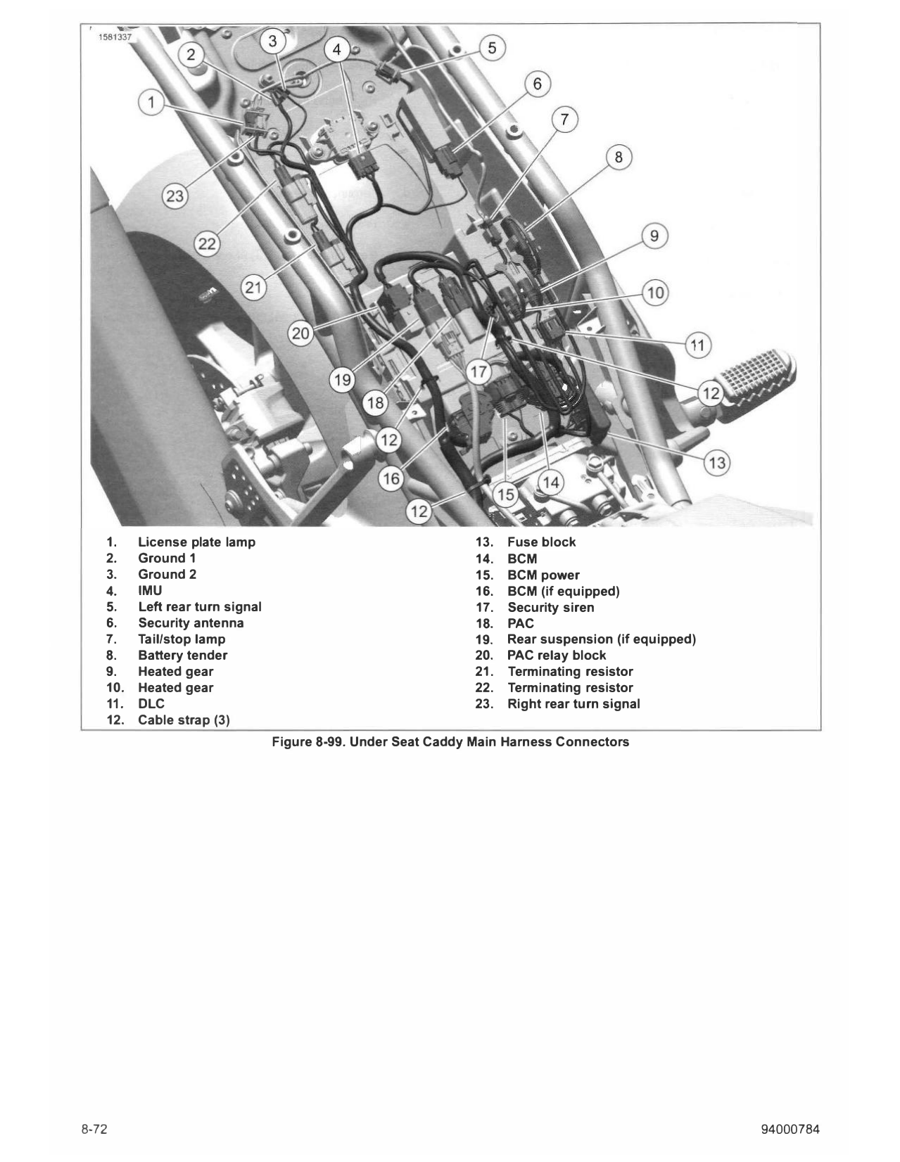
1. License plate lamp 13. Fuse block
2. Ground 1 14. BCM
3. Ground 2 15. BCM power
4. IMU 16. BCM (if equipped)
5. Left rear turn signal 17. Security siren
6. Security antenna 18. PAC
7. Tail/stop lamp 19. Rear suspension (if equipped)
8. Battery tender 20. PAC relay block
9. Heated gear 21. Terminating resistor
10. Heated gear 22. Terminating resistor
11. DLC 23. Right rear turn signal
12. Cable strap (3)
Figure 8-99. Under Seat Caddy Main Harness Connectors
8-72 94000784
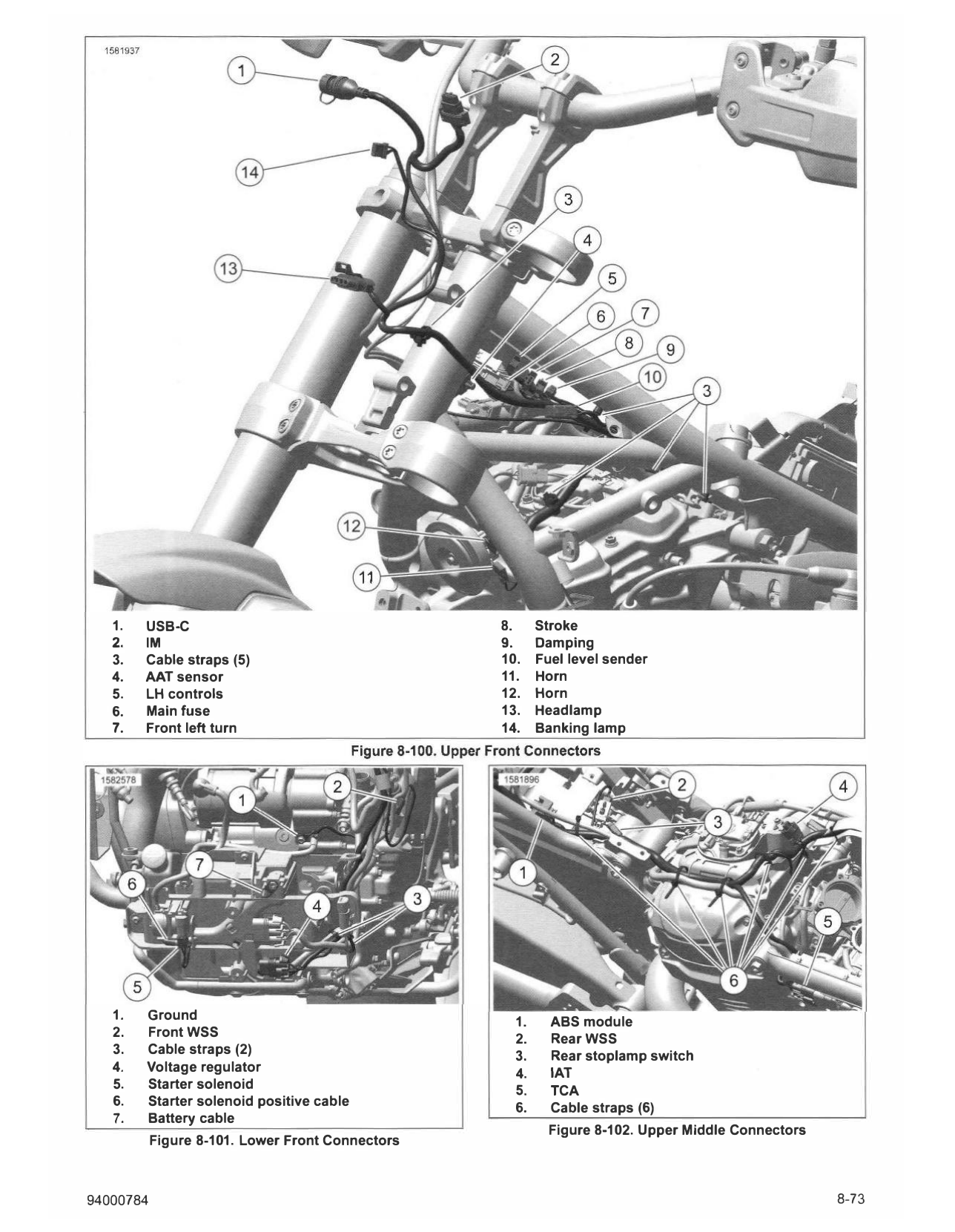
1. USB-C 8. Stroke
2. IM 9. Damping
3. Cable straps (5) 10. Fuel level sender
4. AAT sensor 11. Horn
5. LH controls 12. Horn
6. Main fuse 13. Headlamp
7. Front left turn 14. Banking lamp
1. Ground 1. ABS module
2. FrontWSS 2. RearWSS
3. Cable straps (2)
3. Rear stoplamp switch
4. Voltage regulator 4. IAT
5. Starter solenoid 5. TCA
6. Starter solenoid positive cable 6. Cable straps (6)
7. Battery cable
Figure 8-102. Upper Middle Connectors
Figure 8-101. Lower Front Connectors
94000784 8-73
COMPLETE 4. Install seat. See SEAT (Page 3-113).
1. Install seat base assembly. See TAIL SECTION 5. Install main fuse. See POWER DISCONNECT
(Page 3-114). (Page 8-4).
2. Install air box. See AIR BOX (Page 6-3). 6. Install right side steering head cover. See SIDE COVERS
(Page 3-52).
3. Install fuel tank. See FUEL TANK (Page 6-13).
8-74 94000784