8.43 Battery Tray
Fragment manuala — str. 445
📋 Tekst do skopiowania (OCR/wyszukiwanie)
BATTERY TRAY 8.43
PREPARE
1. Remove main fuse. See POWER DISCON NECT
(Page 8-4).
2. Remove skid plate. See SKID PLATE (Page 3-92).
3. Remove engine guard (if equipped). See ENG INE
GUARDS (Page 3-94).
4. Remove voltage regulator and bracket. See VOLTAGE
REGULATOR (Page 8-13).
5. Remove battery. See INSPECT BAT TERY (Page 2-38).
6. Remove coolant overflow tank. See COOLAN T
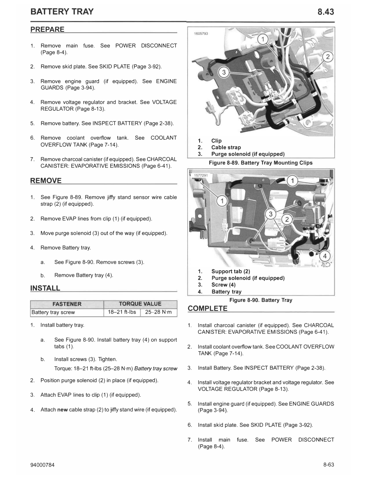
1. Clip
OVERFLOW TANK (Page 7-14).
2. Cable strap
3. Purge solenoid (if equipped)
7. Remove charcoal canister (if equipped). See CHARCOAL
Figure 8-89. Battery Tray Mounting Clips
CAN ISTER: EVAPORATIVE EMISSIONS (Page 6-41 ).
REMOVE
1. See Figure 8-89. Remove jiffy stand sensor wire cable
strap (2) (if equipped).
2. Remove EVAP lines from clip (1) (if equipped).
3. Move purge solenoid (3) out of the way (if equipped).
4. Remove Battery tray.
a. See Figure 8-90. Remove screws (3).
1. Support tab (2)
b. Remove Battery tray (4).
2. Purge solenoid (if equipped)
3. Screw (4)
INSTALL 4. Battery tray
Figure 8-90. Battery Tray
FASTENER TORQUE VALUE
Battery tray screw 18-21 ft-lbs 25--28 N·m
COMPLETE
1. Install battery tray. 1. Install charcoal canister (if equipped). See CHARCOAL
CANISTER: EVAPORATIVE EMISSION S (Page 6-41 ).
a. See Figure 8-90. Install battery tray (4) on support
tabs (1). 2. Install coolant overflow tank. See COOLAN T OVERFLOW
TANK (Page 7-14).
b. Install screws (3). Tighten.
Torque: 18-21 ft-lbs (25-28 N·m) Battery tray screw 3. Install Battery. See IN SPECT BATTERY (Page 2-38).
2. Position purge solenoid (2) in place (if equipped). 4. Install voltage regulator bracket and voltage regulator. See
VOLTAGE REGULATOR (Page 8-13).
3. Attach EVAP lines to clip (1) (if equipped).
5. Install engine guard (if equipped). See EN GINE GUARDS
4. Attach new cable strap (2) to jiffy stand wire (if equipped). (Page 3-94).
6. Install skid plate. See SKID PLATE (Page 3-92).
7. Install main fuse. See POWER DISCONNECT
(Page 8-4).
94000784 8-63