8.32 Camshaft Timing Sensors
Fragment manuala — str. 430
📋 Tekst do skopiowania (OCR/wyszukiwanie)
CAMSHAFT TIMING SENSORS 8.32
PREPARE
1. Purge fuel line. See PURGE FUEL LINE (Page 6-9).
2. Remove seat. See SEAT (Page 3-113).
3. Remove main fuse. See POWER DISCONNECT
(Page 8-4).
4. Remove middle side covers (2). See SIDE COVERS
(Page 3-52).
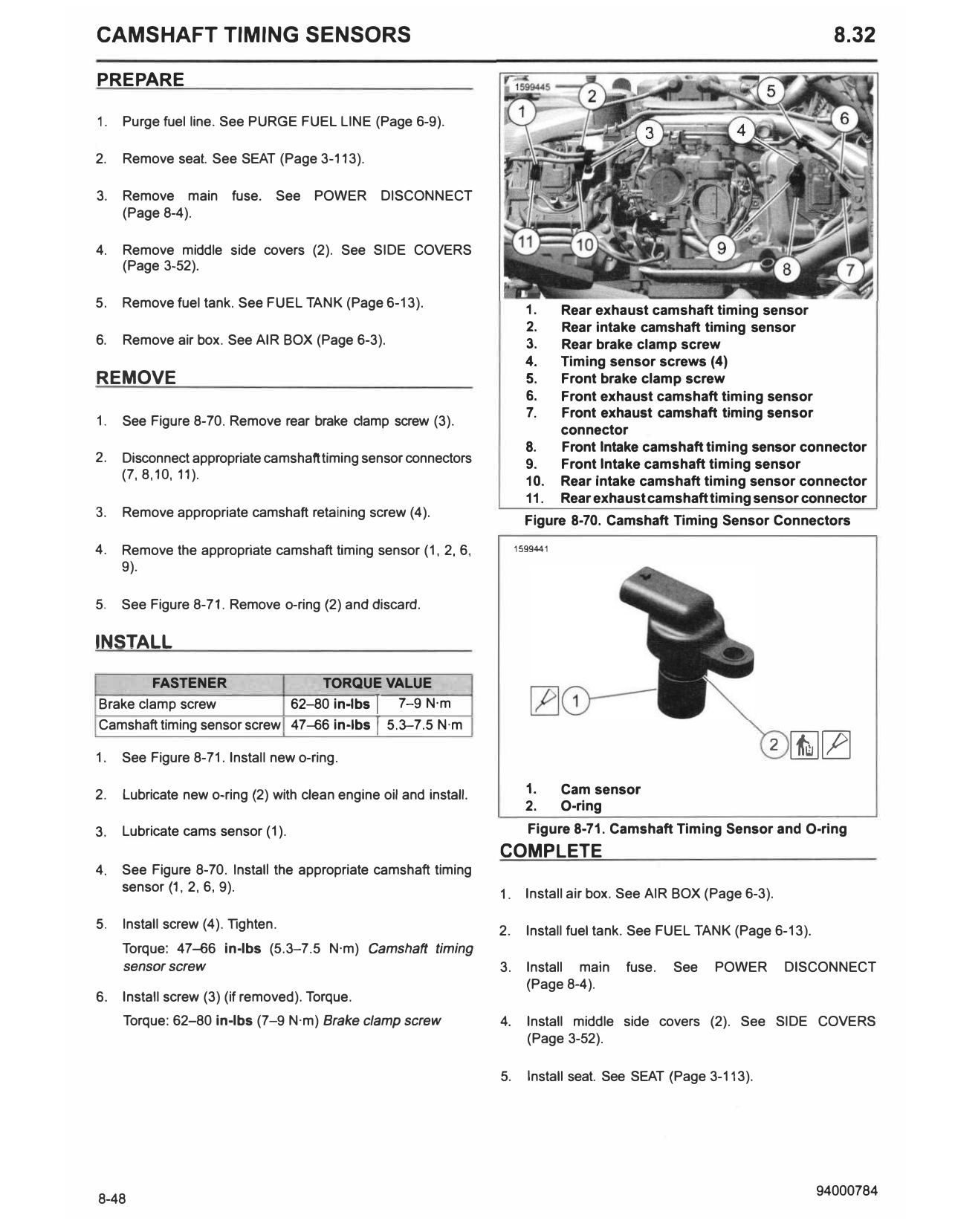
5. Remove fuel tank. See FUEL TANK (Page 6-13). 1. Rear exhaust camshaft timing sensor
2. Rear intake camshaft timing sensor
6. Remove air box. See AIR BOX (Page 6-3). 3. Rear brake clamp screw
4. Timing sensor screws (4)
REMOVE 5. Front brake clamp screw
6. Front exhaust camshaft timing sensor
7. Front exhaust camshaft timing sensor
1. See Figure 8-70. Remove rear brake clamp screw (3).
connector
8. Front Intake camshaft timing sensor connector
2. Disconnect appropriate camshaft timing sensor connectors 9. Front Intake camshaft timing sensor
(7, 8, 10, 11). 10. Rear Intake camshaft timing sensor connector
11. Rear exhaust camshaft timing sensor connector
3. Remove appropriate camshaft retaining screw (4).
Figure 8-70. Camshaft Timing Sensor Connectors
4. Remove the appropriate camshaft timing sensor (1, 2, 6, 1599441
9).
5. See Figure 8-71. Remove o-ring {2) and discard.
INSTALL
FASTENER TORQUE VALUE
Brake clamp screw 62-80 in-lbs I
7-9 N·m
Camshaft timing sensor screw 47-66 in-lbs I
5.3-7.5 N·m
1. See Figure 8-71. Install new o-ring.
2 [i][Z]
2. Lubricate new o-ring {2) with clean engine oil and install. 1. Cam sensor
2. O-ring
3. Lubricate cams sensor (1). Figure 8-71. Camshaft Timing Sensor and O-ring
COMPLETE
4. See Figure 8-70. Install the appropriate camshaft timing
sensor {1, 2, 6, 9).
1. Install air box. See AIR BOX (Page 6-3).
5. Install screw (4). Tighten.
2. Install fuel tank. See FUEL TANK (Page 6-13).
Torque: 47-66 in-lbs (5.3-7.5 N·m) Camshaft timing
sensor screw 3. Install main fuse. See POWER DISCONNEC T
{Page 8-4).
6. Install screw (3) (if removed). Torque.
Torque: 62-80 in-lbs (7-9 N·m) Brake clamp screw 4. Install middle side covers (2). See SIDE COVERS
(Page 3-52).
5. Install seat. See SEAT {Page 3-113).