8.17 Cornering Lamp
Fragment manuala — str. 412–413
📋 Tekst do skopiowania (OCR/wyszukiwanie)
CORNERING LAMP 8.17
PREPARE
4. Test headlamp for proper operation.
1. Remove main fuse. See POWER DISCONNECT
(Page 8-4).
ALIGN AND ADJUST
2. Remove fairing. See FAIRING (Page 3-89). FASTENER TORQUE VALUE
Bank angle light screws 71-89 in-lbs 8-10 N·m
3. Remove cowl. See COWL (Page 3-86).
Align headlamp. See Align in HEADLAMP (Page 8-28).
REMOVE Check Bank Angle Light Alignment (If equipped)
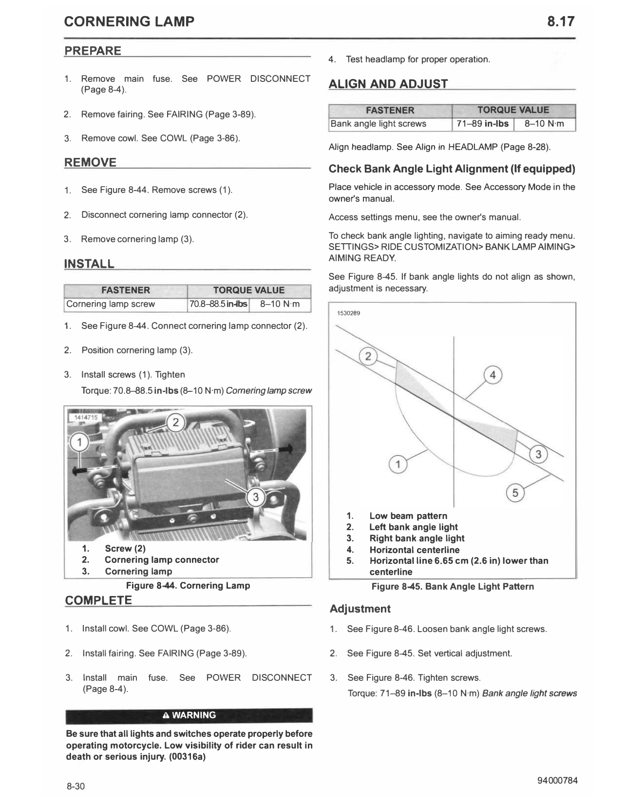
1. See Figure 8-44. Remove screws (1). Place vehicle in accessory mode. See Accessory Mode in the
owner's manual.
2. Disconnect cornering lamp connector (2). Access settings menu, see the owner's manual.
3. Remove cornering lamp (3). To check bank angle lighting, navigate to aiming ready menu.
SETTINGS> RIDE CUSTOMIZATION> BANK LAMP AIMING>
AIMING READY.
INSTALL
See Figure 8-45. If bank angle lights do not align as shown,
FASTENER TORQUE VALUE adjustment is necessary.
Cornering lamp screw 70.8--88.5in-lbs 8-10 N·m
1530289
1. See Figure 8-44. Connect cornering lamp connector (2).
2. Position cornering lamp (3).
3. Install screws (1). Tighten
Torque: 70.8--88.5 in-lbs (8-10 N·m) Cornering lamp screw
1. Low beam pattern
2. Left bank angle light
3. Right bank angle light
1. Screw (2) 4. Horizontal centerline
2. Cornering lamp connector 5. Horizontal line 6.65 cm (2.6 in) lower than
3. Cornering lamp centerline
Figure 8-44. Cornering Lamp Figure 8-45. Bank Angle Light Pattern
COMPLETE
Adjustment
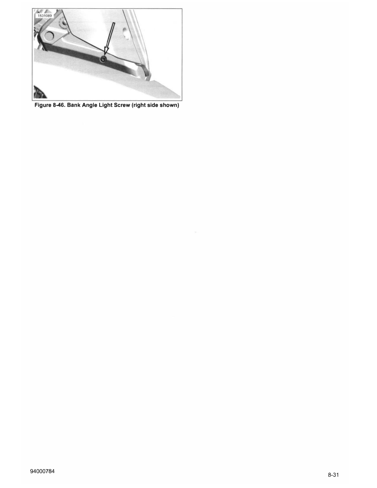
1. Install cowl. See COWL (Page 3-86). 1. See Figure 8-46. Loosen bank angle light screws.
2. Install fairing. See FAIRING (Page 3-89). 2. See Figure 8-45. Set vertical adjustment.
3. Install main fuse. See POWER DISCONNECT 3. See Figure 8-46. Tighten screws.
(Page 8-4). Torque: 71-89 in-lbs (8-10 N·m) Bank angle light screws
A WARNING
Be sure that all lights and switches operate properly before
operating motorcycle. Low visibility of rider can result in
death or serious injury. (00316a)
Figure 8-46. Bank Angle Light Screw (right side shown)