8.13 Instrument Module (Im)
Fragment manuala — str. 406–407
📋 Tekst do skopiowania (OCR/wyszukiwanie)
INSTRUMENT MODULE (IM) 8.13
PREPARE 3. See Figure 8-35. Rotate IM (1) and connect IM connector
(2).
1. Remove main fuse. See POWER DISCONNECT
(Page 8-4).
2. Remove fairing. See FAIRING (Page 3-89).
3. Remove cowl. See COWL (Page 3-86).
REMOVE
1. NOTE
Rotating IM to mid-way point aligns keyways.
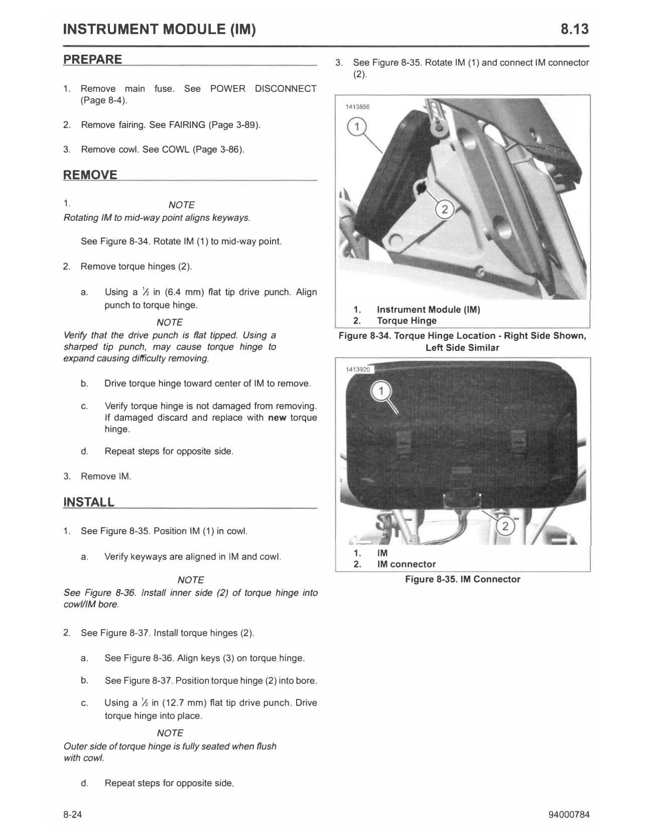
See Figure 8-34. Rotate IM (1) to mid-way point.
2. Remove torque hinges (2).
a. Using a ½ in (6.4 mm) flat tip drive punch. Align
punch to torque hinge. 1. Instrument Module (IM)
NOTE 2. Torque Hinge
Verify that the drive punch is flat tipped. Using a Figure 8-34. Torque Hinge Location - Right Side Shown,
sharped tip punch, may cause torque hinge to Left Side Similar
expand causing difficulty removing.
b. Drive torque hinge toward center of IM to remove.
c. Verify torque hinge is not damaged from removing.
If damaged discard and replace with new torque
hinge.
d. Repeat steps for opposite side.
3. Remove IM.
INSTALL
1. See Figure 8-35. Position IM (1) in cowl.
a. Verify keyways are aligned in IM and cowl. 1. IM
2. IM connector
NOTE Figure 8-35. IM Connector
See Figure 8-36. Install inner side (2) of torque hinge into
cowl/lM bore.
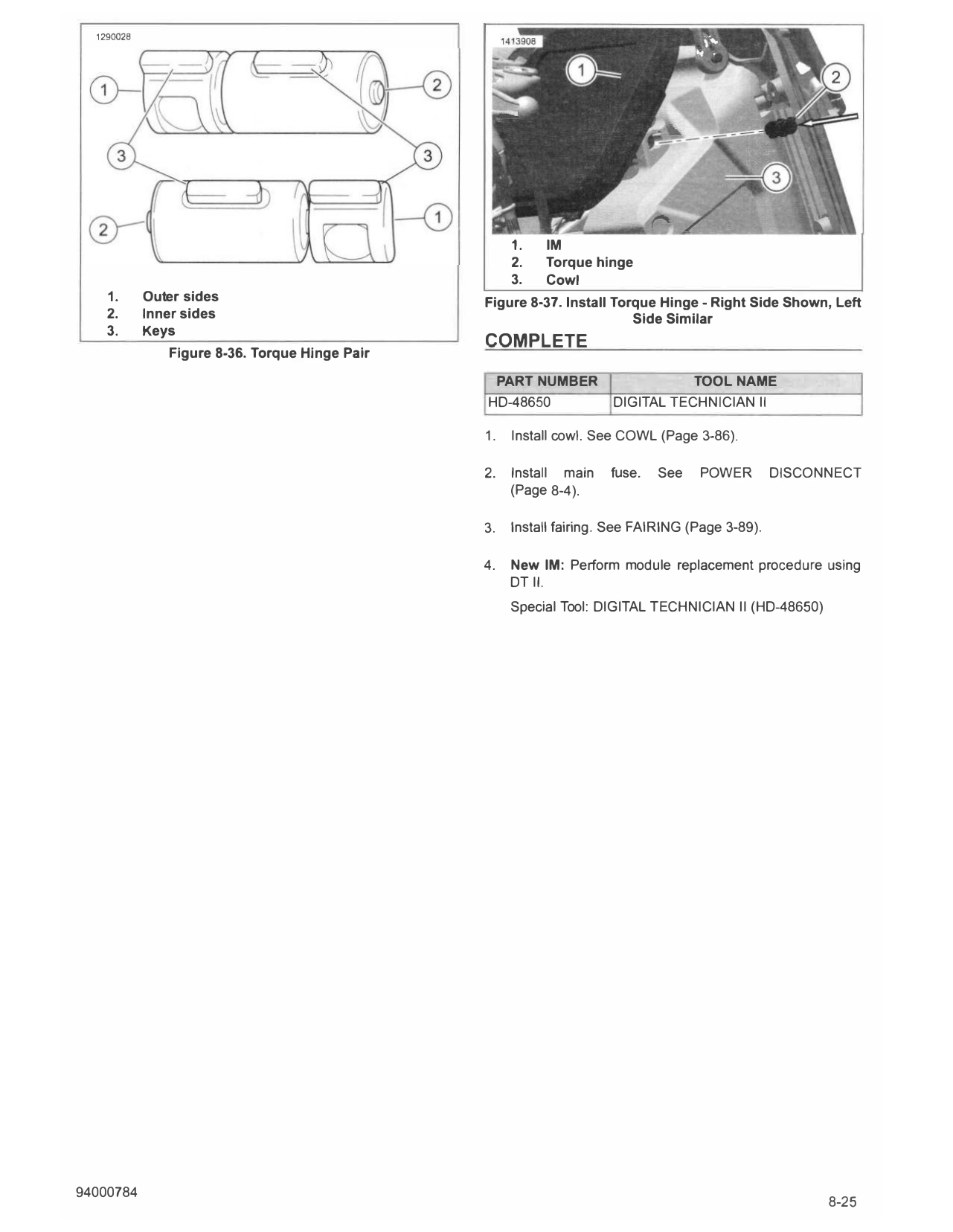
2. See Figure 8-37. Install torque hinges (2).
a. See Figure 8-36. Align keys (3) on torque hinge.
b. See Figure 8-37. Position torque hinge (2) into bore.
c. Using a ½ in (12.7 mm) flat tip drive punch. Drive
torque hinge into place.
NOTE
Outer side of torque hinge is fully seated when flush
with cowl.
d. Repeat steps for opposite side.
8-24 94000784
1290028
1. IM
2. Torque hinge
3. Cowl
1. Outer sides Figure 8-37. Install Torque Hinge - Right Side Shown, Left
2. Inner sides Side Similar
3. Keys
COMPLETE
Figure 8-36. Torque Hinge Pair
PART NUMBER TOOL NAME
HD-48650 DIGITAL TECHNICIAN II
1. Install cowl. See COWL (Page 3-86).
2. Install main fuse. See POWER DISCONNECT
(Page 8-4).
3. Install fairing. See FAIRING (Page 3-89).
4. New IM: Perform module replacement procedure using
DT II.
Special Tool: DIGITAL TECHNICIAN II (HD-48650)