8.12 Right Hand Control Module (Rhcm)
Fragment manuala — str. 404–405
📋 Tekst do skopiowania (OCR/wyszukiwanie)
RIGHT HAND CONTROL MODULE (RHCM) 8.12
PREPARE 4. Install handlebar end cap. Tighten.
Torque: 124-177 in-lbs (14-20 N·m) Handlebar End Cap
1. Remove right side steering head cover. See SIDE
COVERS (Page 3-52). 5. See Figure 8-32. Install rear cover (2).
2. Remove main fuse. See POWER DISCONNECT a. Position rear cover.
(Page 8-4).
b. Install screws (1). Tighten.
3. Without draining brake fluid, loosen brake hand control Torque: 6----8 in-lbs (0.65--0.9 N·m) RHCM rear cover
assembly and move away from RHCM. See FRONT screw
BRAKE MASTER CYLINDER (Page 3-29). c. Install cable strap mount (3).
4. If equipped: Remove right deflector. See HANDLEBAR
WIND DEFLECTORS (Page 3-96).
REMOVE
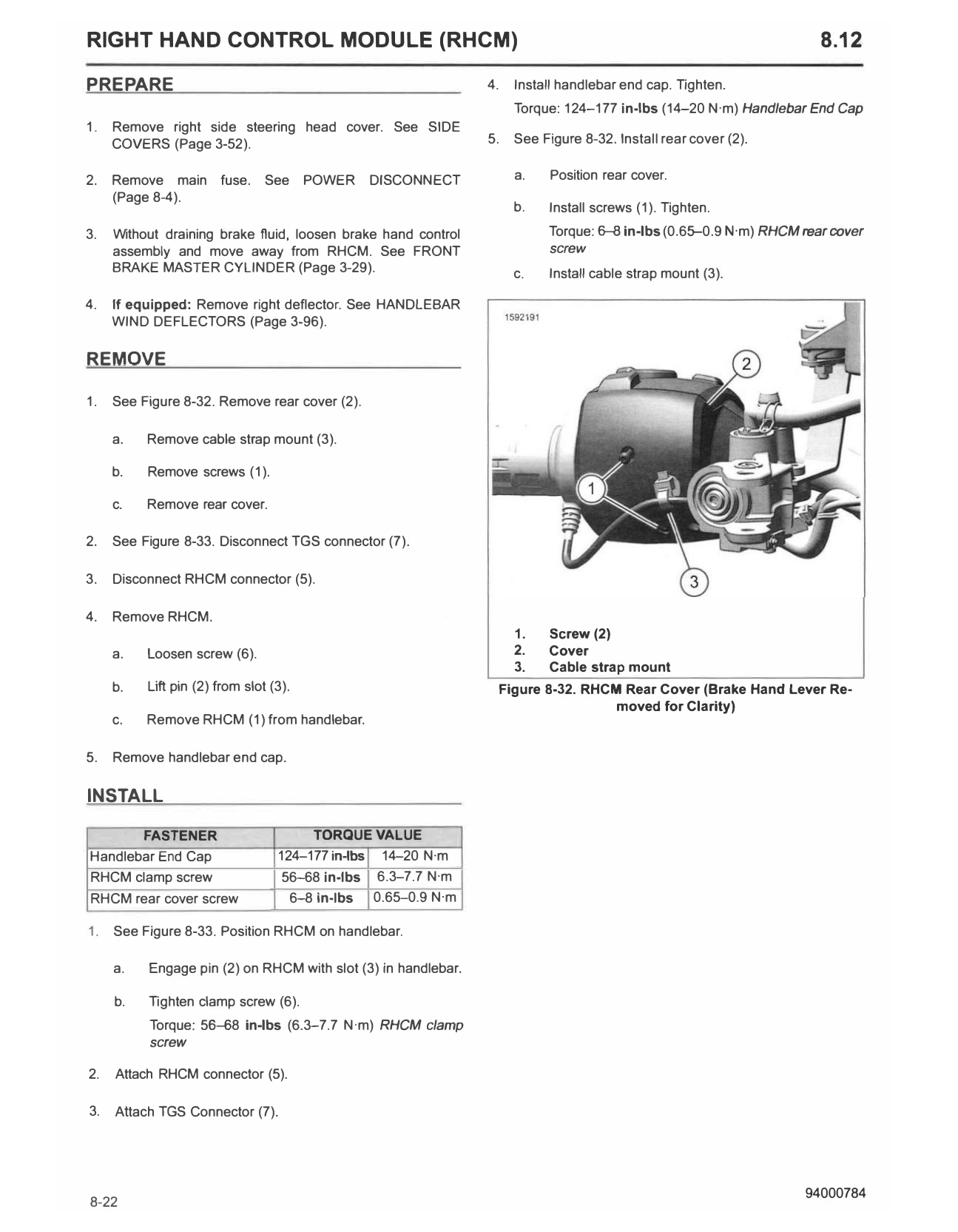
1. See Figure 8-32. Remove rear cover (2).
a. Remove cable strap mount (3).
b. Remove screws (1).
c. Remove rear cover.
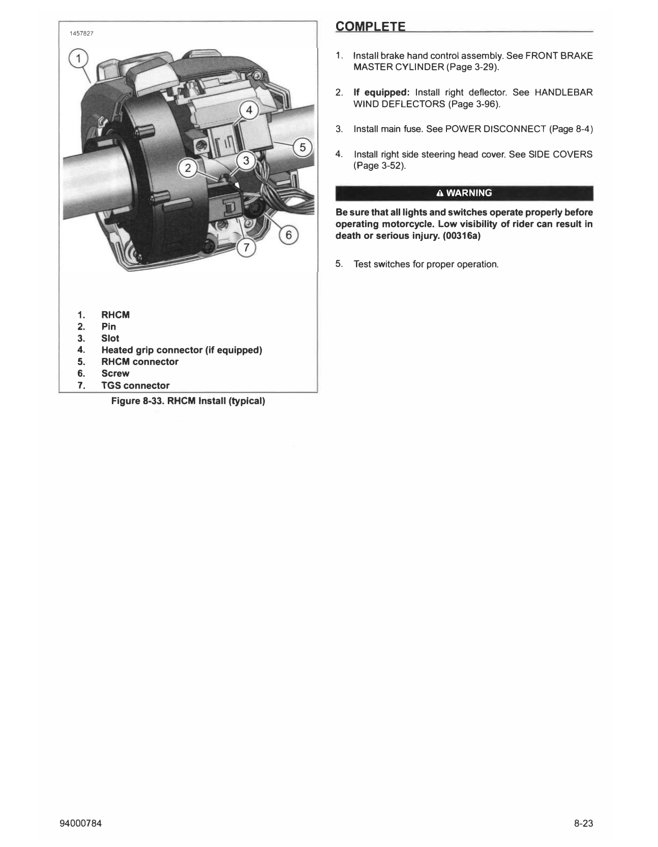
2. See Figure 8-33. Disconnect TGS connector (7).
3. Disconnect RHCM connector (5).
4. Remove RHCM.
1. Screw (2)
a. Loosen screw (6). 2. Cover
3. Cable strap mount
b. Lift pin (2) from slot (3). Figure 8-32. RHCM Rear Cover (Brake Hand Lever Re
moved for Clarity)
c. Remove RHCM (1) from handlebar.
5. Remove handlebar end cap.
INSTALL
FASTENER TORQUE VALUE
Handlebar End Cap 124-177in-lbs 14-20 N·m
RHCM clamp screw 56-68 in-lbs 6.3-7.7 N·m
RHCM rear cover screw 6-8 in-lbs 0.65--0.9 N·m
1. See Figure 8-33. Position RHCM on handlebar.
a. Engage pin (2) on RHCM with slot (3) in handlebar.
b. Tighten clamp screw (6).
Torque: 5EH58 in-lbs (6.3-7.7 N·m) RHCM clamp
screw
2. Attach RHCM connector (5).
3. Attach TGS Connector (7).
1457827
COMPLETE
1. Install brake hand control assembly. See FRONT BRAKE
MASTER CYLINDER (Page 3-29).
2. If equipped: Install right deflector. See HANDLEBAR
WIND DEFLECTORS (Page 3-96).
3. Install main fuse. See POWER DISCONNECT (Page 8-4)
4. Install right side steering head cover. See SIDE COVERS
(Page 3-52).
A WARNING
Be sure that all lights and switches operate properly before
operating motorcycle. Low visibility of rider can result in
death or serious injury. (00316a)
5. Test switches for proper operation.
1. RHCM
2. Pin
3. Slot
4. Heated grip connector (if equipped)
5. RHCM connector
6. Screw
7. TGS connector
Figure 8-33. RHCM Install (typical)
94000784 8-23