7.5 Coolant
Fragment manuala — str. 368–370
📋 Tekst do skopiowania (OCR/wyszukiwanie)
COOLANT 7.5
PREPARE
1. Remove skid plate. See SKID PLATE (Page 3-92).
2. Remove right engine guard. See ENGINE GUARDS
(Page 3-94).
3. Remove right lower fairing. See FAIRING LOWERS
(Page 3-90).
4. If bleeding system remove side mount ignition coil and
bracket. See IGNITION COIL (Page 8-16).
CHECK COOLANT LEVEL
A CAUTION
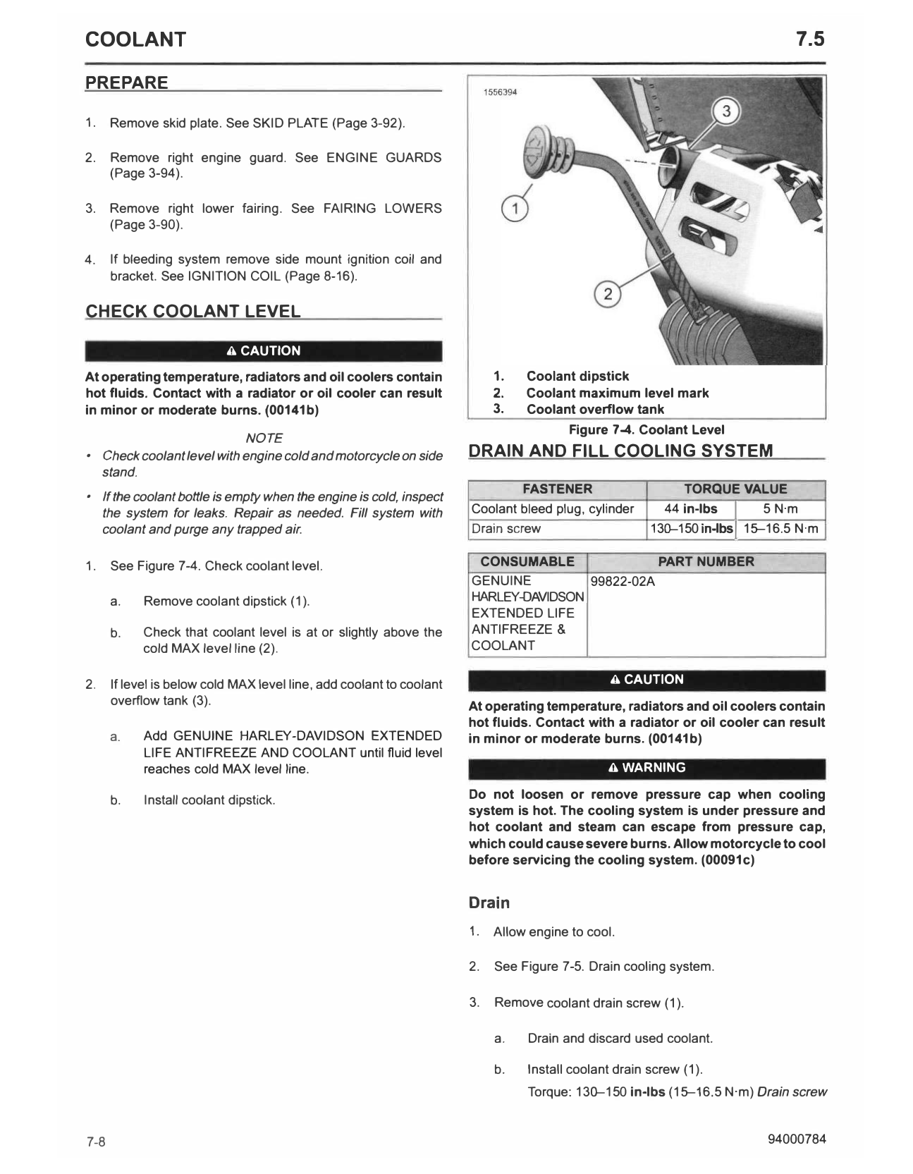
At operating temperature, radiators and oil coolers contain 1. Coolant dipstick
hot fluids. Contact with a radiator or oil cooler can result 2. Coolant maximum level mark
in minor or moderate bums. (00141b) 3. Coolant overflow tank
Figure 7-4. Coolant Level
NOTE
• Check coolant level with engine cold and motorcycle on side DRAIN AND FILL COOLING SYSTEM
stand.
FASTENER TORQUE VALUE
• If the coolant bottle is empty when the engine is cold, inspect
the system for leaks. Repair as needed. Fill system with
coolant and purge any trapped air.
Coolant bleed plug, cylinder
Drain screw
44 in-lbs I5 N·m
130-150in-lbsl 15-16.5 N·m
1. See Figure 7-4. Check coolant level. CONSUMABLE PART NUMBER
GENUINE 99822-02A
a. Remove coolant dipstick (1). HARLEY-DAVIDSON
EXTENDED LIFE
b. Check that coolant level is at or slightly above the ANTIFREEZE &
cold MAX level line (2). COOLANT
2. If level is below cold MAX level line, add coolant to coolant A CAUTION
overflow tank (3). At operating temperature, radiators and oil coolers contain
hot fluids. Contact with a radiator or oil cooler can result
a. Add GENUINE HARLEY-DAVIDSON EXTENDED in minor or moderate burns. (00141b)
LIFE ANTIFREEZE AND COOLANT until fluid level
reaches cold MAX level line. A WARNING
b. Install coolant dipstick. Do not loosen or remove pressure cap when cooling
system is hot. The cooling system is under pressure and
hot coolant and steam can escape from pressure cap,
which could cause severe burns. Allow motorcycle to cool
before servicing the cooling system. (00091c)
Drain
1. Allow engine to cool.
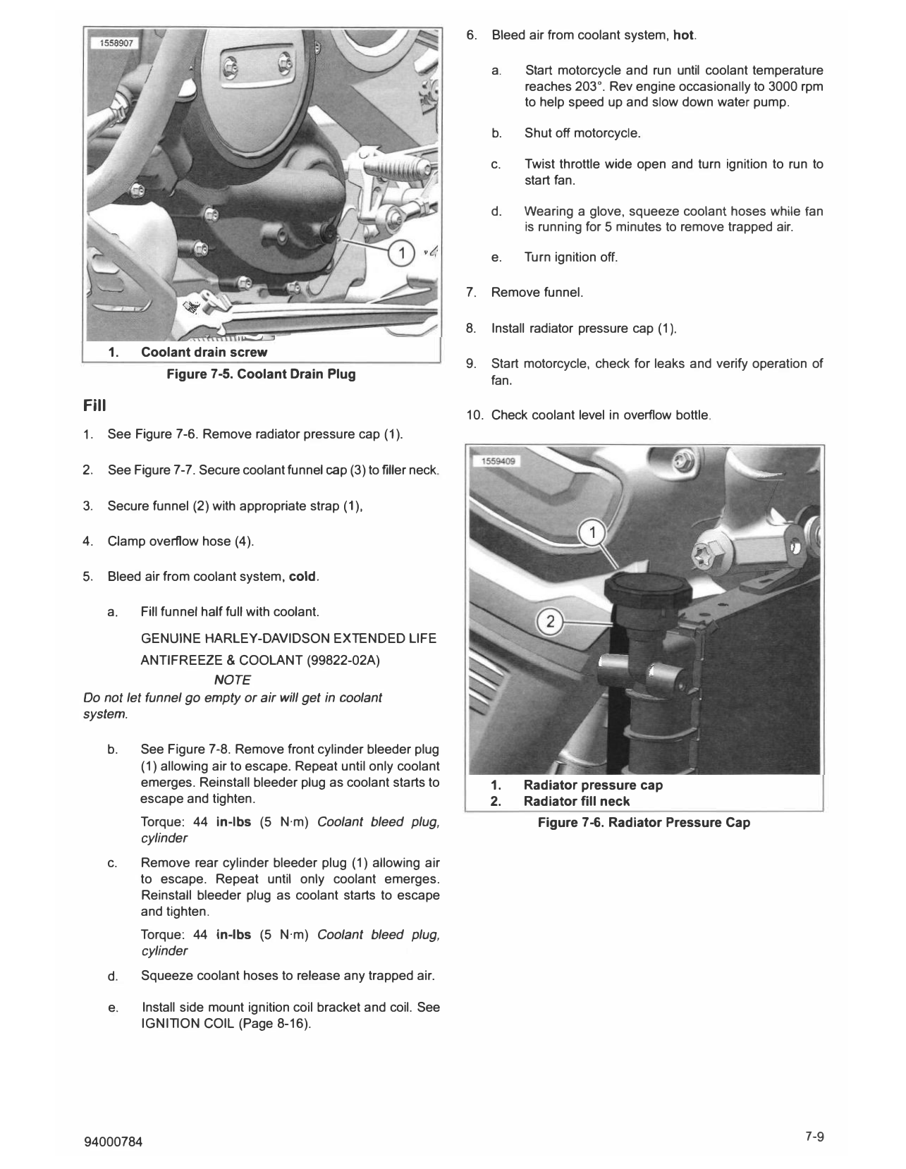
2. See Figure 7-5. Drain cooling system.
3. Remove coolant drain screw (1).
a. Drain and discard used coolant.
b. Install coolant drain screw (1).
Torque: 130-150 in-lbs (15-16.5 N·m) Drain screw
7-8 94000784
6. Bleed air from coolant system, hot.
a. Start motorcycle and run until coolant temperature
reaches 203 °. Rev engine occasionally to 3000 rpm
to help speed up and slow down water pump.
b. Shut off motorcycle.
c. Twist throttle wide open and turn ignition to run to
start fan.
d. Wearing a glove, squeeze coolant hoses while fan
is running for 5 minutes to remove trapped air.
e. Turn ignition off.
7. Remove funnel.
8. Install radiator pressure cap (1 ).
�
1. Coolant drain screw
9. Start motorcycle, check for leaks and verify operation of
Figure 7-5. Coolant Drain Plug fan.
Fill
10. Check coolant level in overflow bottle.
1. See Figure 7-6. Remove radiator pressure cap (1).
2. See Figure 7-7. Secure coolant funnel cap (3) to filler neck.
3. Secure funnel (2) with appropriate strap (1 ),
4. Clamp overflow hose (4).
5. Bleed air from coolant system, cold.
a. Fill funnel half full with coolant.
GENUINE HARLEY-DAVIDSON EXTENDED LIFE
ANTIFREEZE & COOLANT (99822-02A)
NOTE
Do not let funnel go empty or air will get in coolant
system.
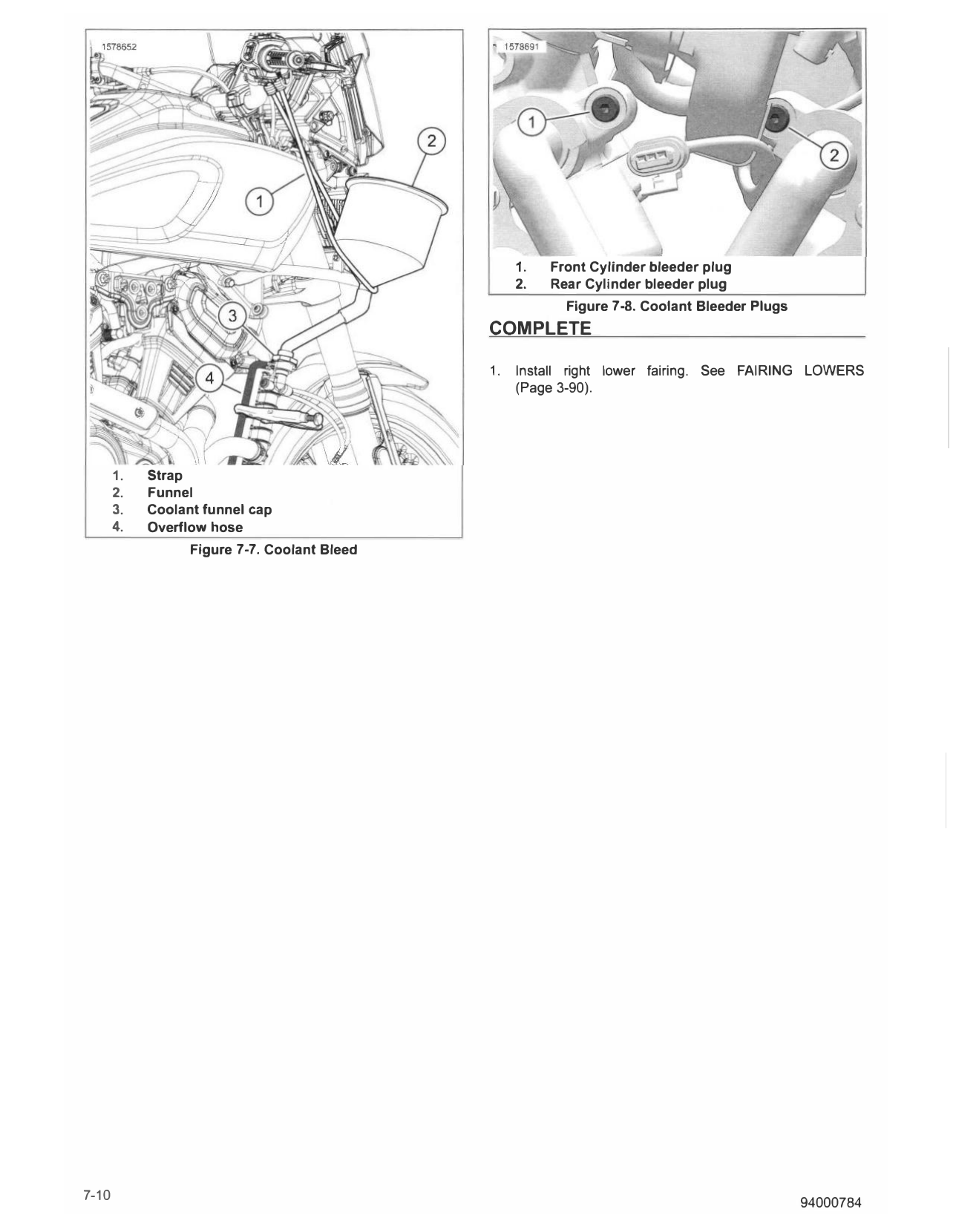
b. See Figure 7-8. Remove front cylinder bleeder plug
(1) allowing air to escape. Repeat until only coolant
emerges. Reinstall bleeder plug as coolant starts to 1. Radiator pressure cap
escape and tighten. 2. Radiator fill neck
Torque: 44 in-lbs (5 N·m) Coolant bleed plug, Figure 7-6. Radiator Pressure Cap
cylinder
c. Remove rear cylinder bleeder plug (1) allowing air
to escape. Repeat until only coolant emerges.
Reinstall bleeder plug as coolant starts to escape
and tighten.
Torque: 44 in-lbs (5 N·m) Coolant bleed plug,
cylinder
d. Squeeze coolant hoses to release any trapped air.
e. Install side mount ignition coil bracket and coil. See
IGNITION COIL (Page 8-16).
94000784 7-9
1. Front Cylinder bleeder plug
2. Rear Cylinder bleeder plug
Figure 7-8. Coolant Bleeder Plugs
COMPLETE
1. Install right lower fairing. See FAIRING LOWERS
(Page 3-90).
1. Strap
2. Funnel
3. Coolant funnel cap
4. Overflow hose
Figure 7-7. Coolant Bleed