6.21 Induction Module
Fragment manuala — str. 342–343
📋 Tekst do skopiowania (OCR/wyszukiwanie)
INDUCTION MODULE 6.21
PREPARE
A WARNING
Gasoline is extremely flammable and highly explosive.
Keep gasoline away from ignition sources which could
result in death or serious injury. See the Safety chapter.
(00635c)
A WARNING
To prevent spray of fuel, purge system of high-pressure
fuel before supply line is disconnected. Gasoline is
extremely flammable and highly explosive, which could
result in death or serious injury. (00275a)
1. Purge fuel line. See PURGE FUEL LINE (Page 6-9).
2. Remove main fuse. See POWER DISCONNECT
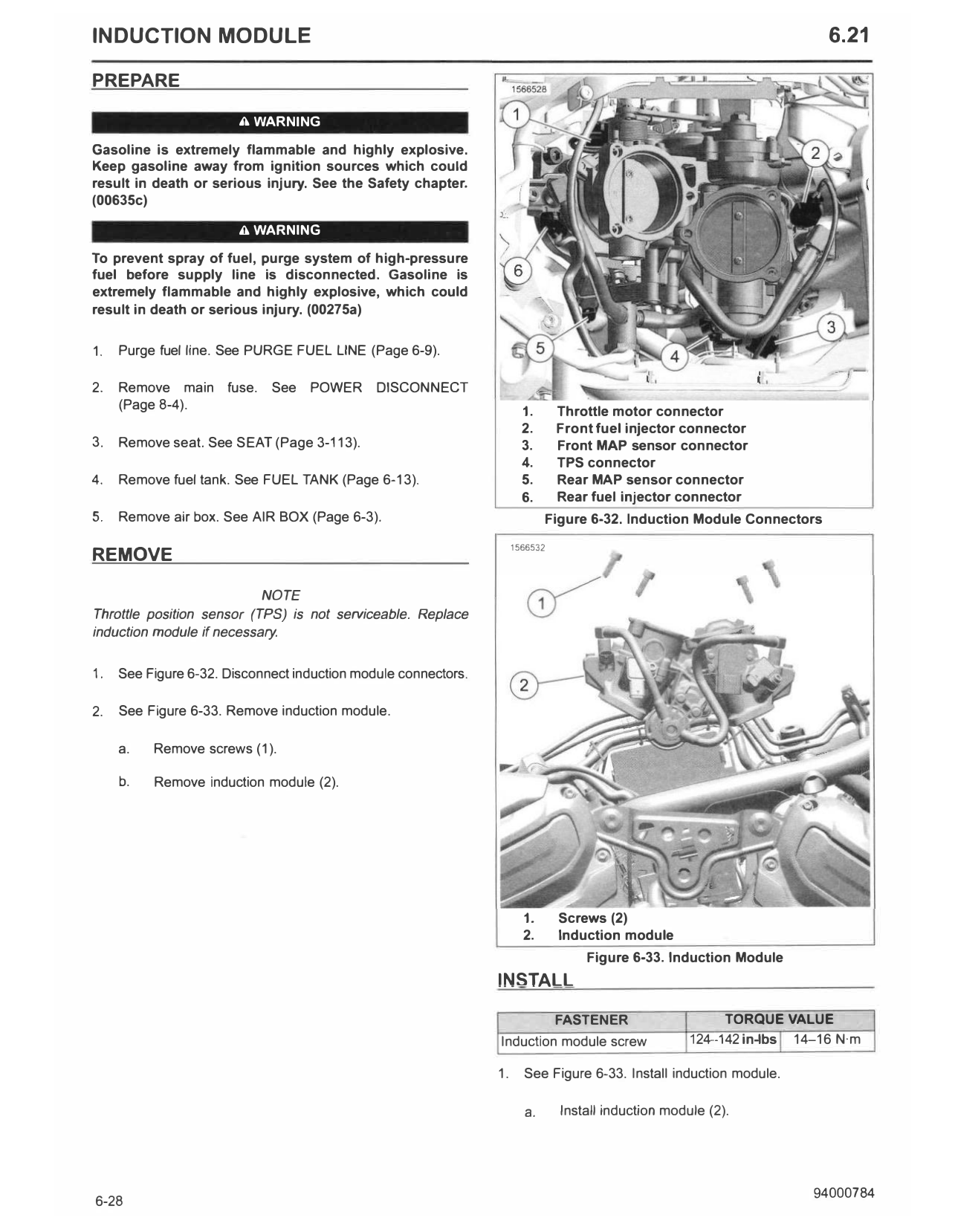
(Page 8-4). 1. Throttle motor connector
2. Front fuel injector connector
3. Remove seat. See SEAT (Page 3-113). 3. Front MAP sensor connector
4. TPS connector
4. Remove fuel tank. See FUEL TANK (Page 6-13). 5. Rear MAP sensor connector
6. Rear fuel injector connector
5. Remove air box. See AIR BOX (Page 6-3). Figure 6-32. Induction Module Connectors
1566532
REMOVE
NOTE
Throttle position sensor (TPS) is not serviceable. Replace
induction module if necessary.
1. See Figure 6-32. Disconnect induction module connectors.
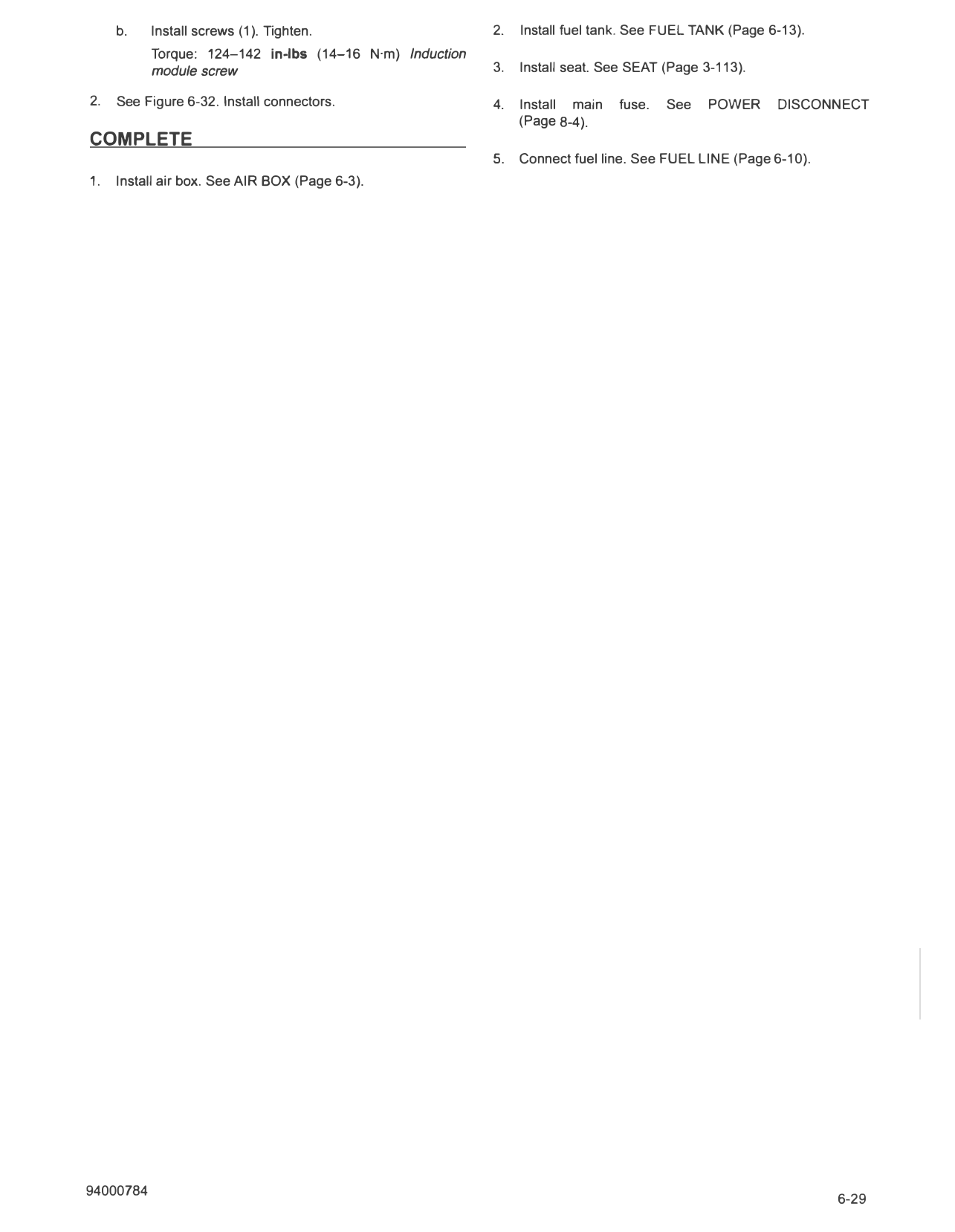
2. See Figure 6-33. Remove induction module.
a. Remove screws (1).
b. Remove induction module (2).
1. Screws (2)
2. Induction module
Figure 6-33. Induction Module
INSTALL
FASTENER TORQUE VALUE
Induction module screw 124--142in�bs 14-16 N·m
1. See Figure 6-33. Install induction module.
a. Install induction module (2).
b. Install screws (1). Tighten. 2. Install fuel tank. See FUEL TANK (Page 6-13).
Torque: 124-142 in-lbs (14-16 N·m) Induction
module screw 3. Install seat. See SEAT (Page 3-113).
2. See Figure 6-32. Install connectors. 4. Install main fuse. See POWER DISCONNEC T
(Page 8-4).
COMPLETE
5. Connect fuel line. See FUEL LINE (Page 6-10).
1. Install air box. See AIR BOX (Page 6-3).