6.17 Manifold Absolute Pressure (Map) Sensor
Fragment manuala — str. 336–337
📋 Tekst do skopiowania (OCR/wyszukiwanie)
MANIFOLD ABSOLUTE PRESSURE (MAP) SENSOR 6.17
PREPARE b. Install screw (2). Tighten.
Torque: 80-97 in-lbs (9-11 N·m) MAP sensor screw
A WARNING
2. Connect MAP sensor connector (3).
Gasoline is extremely flammable and highly explosive.
Keep gasoline away from ignition sources which could
result in death or serious injury. See the Safety chapter.
(00635c)
A WARNING
To prevent spray of fuel, purge system of high-pressure
fuel before supply line is disconnected. Gasoline is
extremely flammable and highly explosive, which could
result in death or serious injury. (00275a)
1. Purge fuel line. See PURGE FUEL LINE (Page 6-9).
2. Remove main fuse. See POWER DISCONNECT
(Page 8-4).
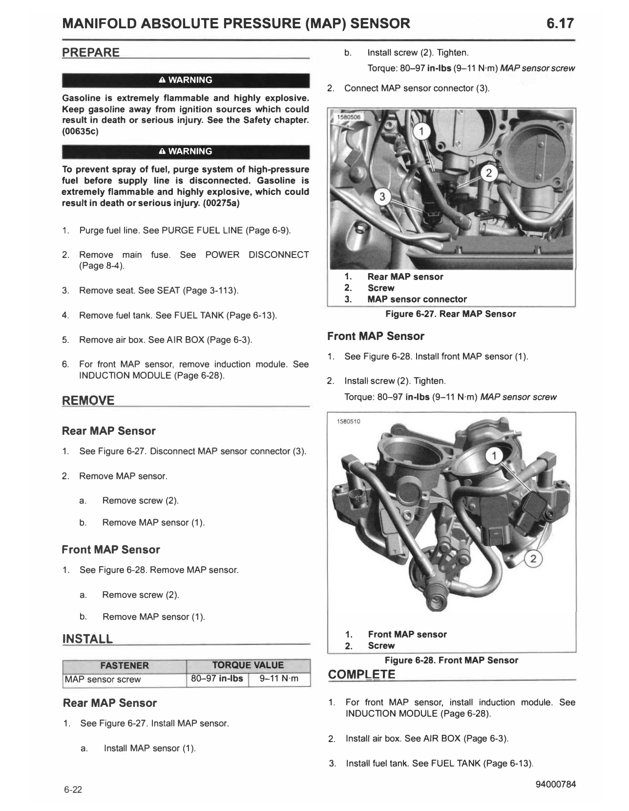
1. Rear MAP sensor
3. Remove seat. See SEAT (Page 3-113). 2. Screw
3. MAP sensor connector
4. Remove fuel tank. See FUEL TANK (Page 6-13). Figure 6-27. Rear MAP Sensor
5. Remove air box. See AIR BOX (Page 6-3). Front MAP Sensor
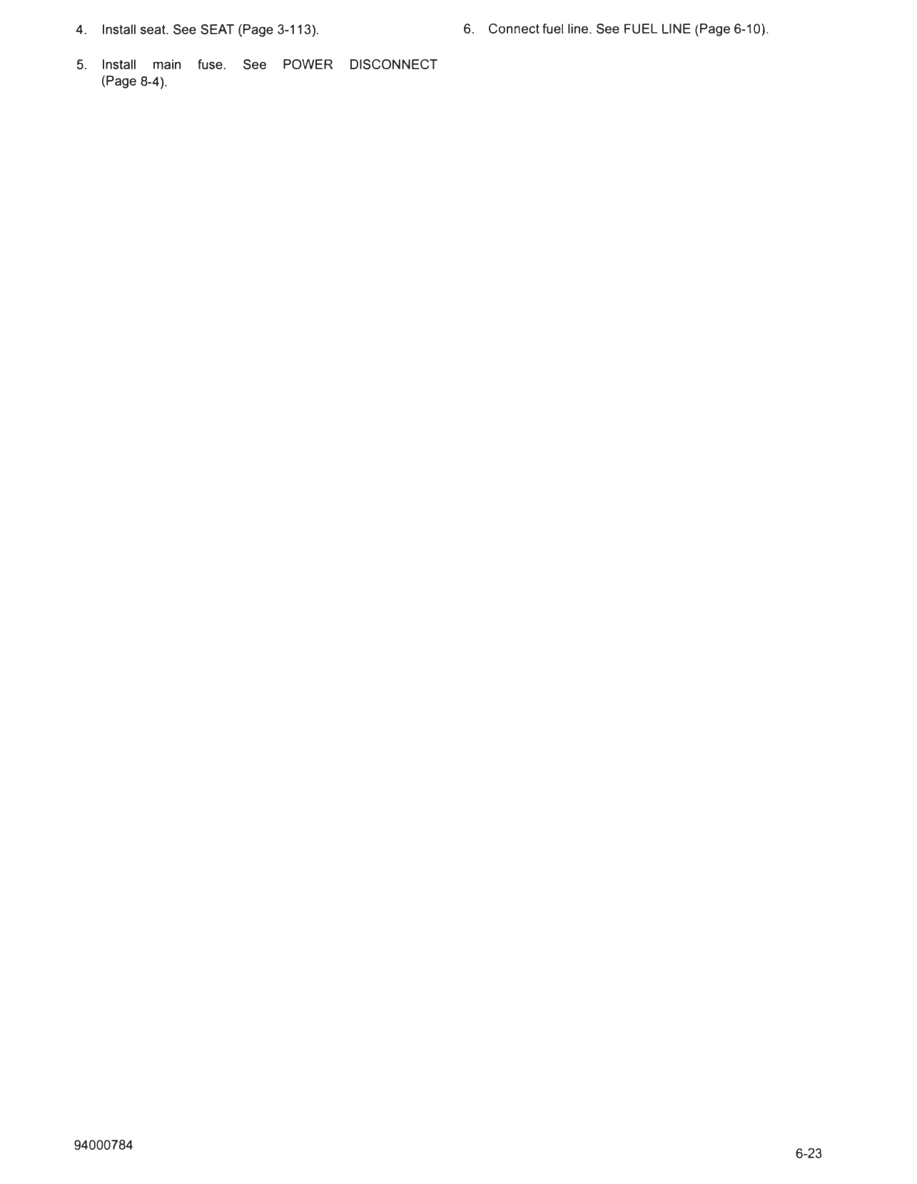
1. See Figure 6-28. Install front MAP sensor (1).
6. For front MAP sensor, remove induction module. See
INDUCTION MODULE (Page 6-28).
2. Install screw (2). Tighten.
Torque: 80-97 in-lbs (9-11 N·m) MAP sensor screw
REMOVE
Rear MAP Sensor
1. See Figure 6-27. Disconnect MAP sensor connector (3).
2. Remove MAP sensor.
a. Remove screw (2).
b. Remove MAP sensor (1).
Front MAP Sensor
1. See Figure 6-28. Remove MAP sensor.
a. Remove screw (2).
b. Remove MAP sensor (1).
1. Front MAP sensor
INSTALL 2. Screw
Figure 6-28. Front MAP Sensor
FASTENER TORQUE VALUE
MAP sensor screw 80-97 in-lbs 9-11 N·m COMPLETE
Rear MAP Sensor 1. For front MAP sensor, install induction module. See
INDUCTION MODULE (Page 6-28).
1. See Figure 6-27. Install MAP sensor.
2. Install air box. See AIR BOX (Page 6-3).
a. Install MAP sensor (1).
3. Install fuel tank. See FUEL TANK (Page 6-13).
4. Install seat. See SEAT (Page 3-113). 6. Connect fuel line. See FUEL LINE (Page 6-10).
5. Install main fuse. See POWER DISCONNECT
(Page 8-4).