5.7 Clutch
Fragment manuala — str. 300–306
📋 Tekst do skopiowania (OCR/wyszukiwanie)
CLUTCH 5.7
PREPARE
1. Remove main fuse. See POWER DISCONNECT
(Page 8-4).
2. Disconnect clutch cable. See CLUTCH CONTROL
(Page 3-82).
3. Drain engine oil. See REPLACE ENGINE OIL AND FILTER
(Page 2-7).
4. Remove center stand (if equipped). See CENTER STAND
(Page 3-111 ).
5. Remove skid plate (if equipped). See SKID PLATE
(Page 3-92).
6. Remove engine guards (if equipped). See ENGINE
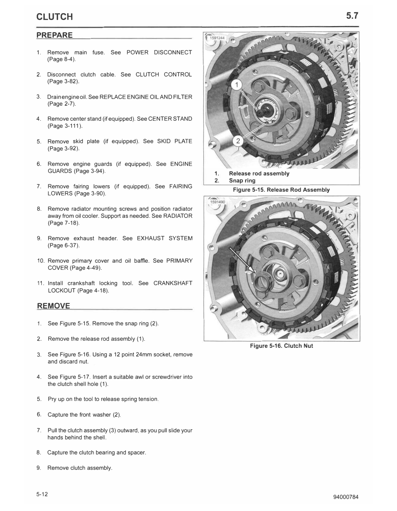
GUARDS (Page 3-94). 1. Release rod assembly
2. Snap ring
7. Remove fairing lowers (if equipped). See FAIRING
Figure 5-15. Release Rod Assembly
LOWERS (Page 3-90).
8. Remove radiator mounting screws and position radiator
away from oil cooler. Support as needed. See RADIATOR
(Page 7-18).
9. Remove exhaust header. See EXHAUST SYSTEM
(Page 6-37).
10. Remove primary cover and oil baffle. See PRIMARY
COVER (Page 4-49).
11. Install crankshaft locking tool. See CRANKSHAFT
LOCKOUT (Page 4-18).
REMOVE
1. See Figure 5-15. Remove the snap ring (2).
2. Remove the release rod assembly (1).
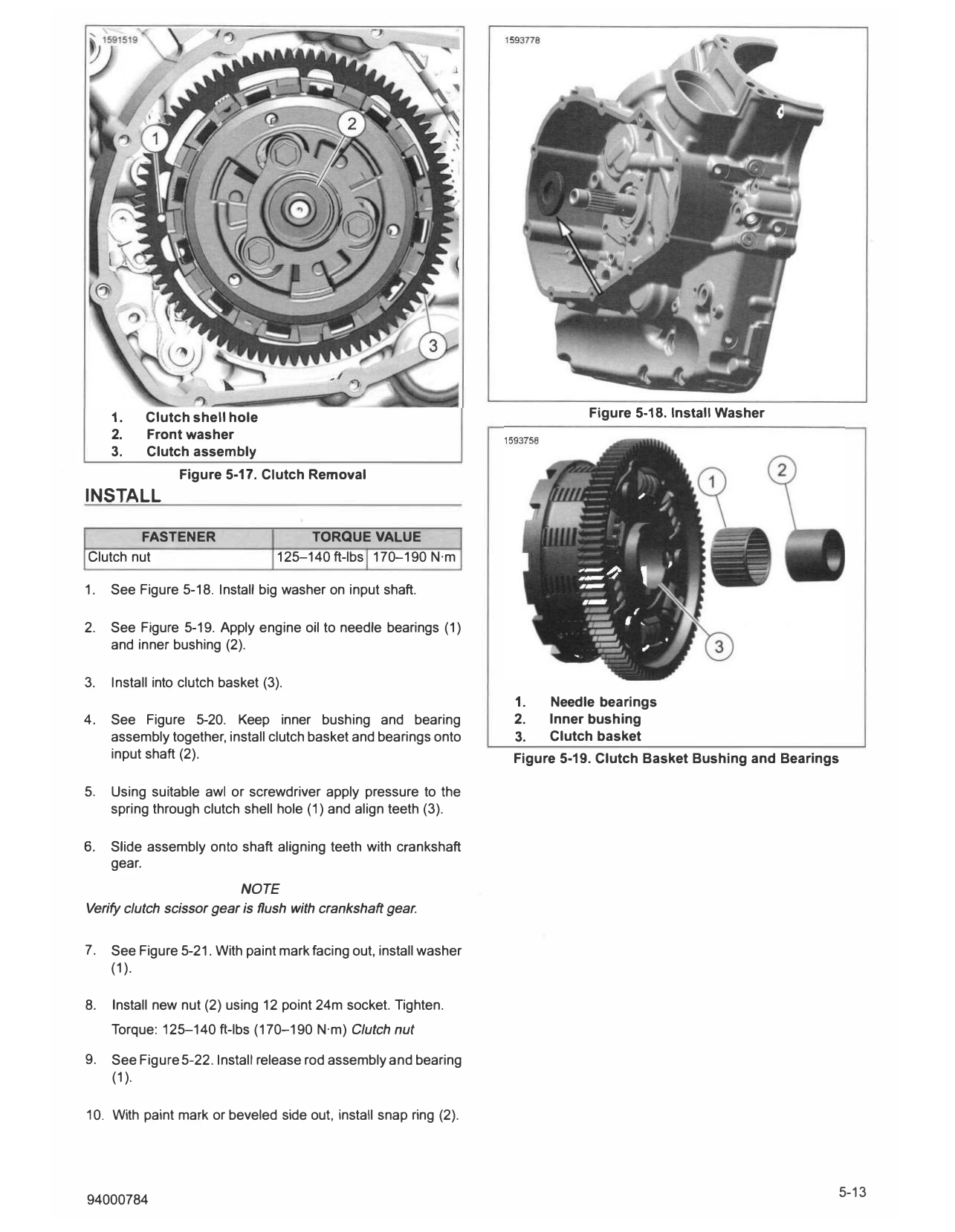
Figure 5-16. Clutch Nut
3. See Figure 5-16. Using a 12 point 24mm socket, remove
and discard nut.
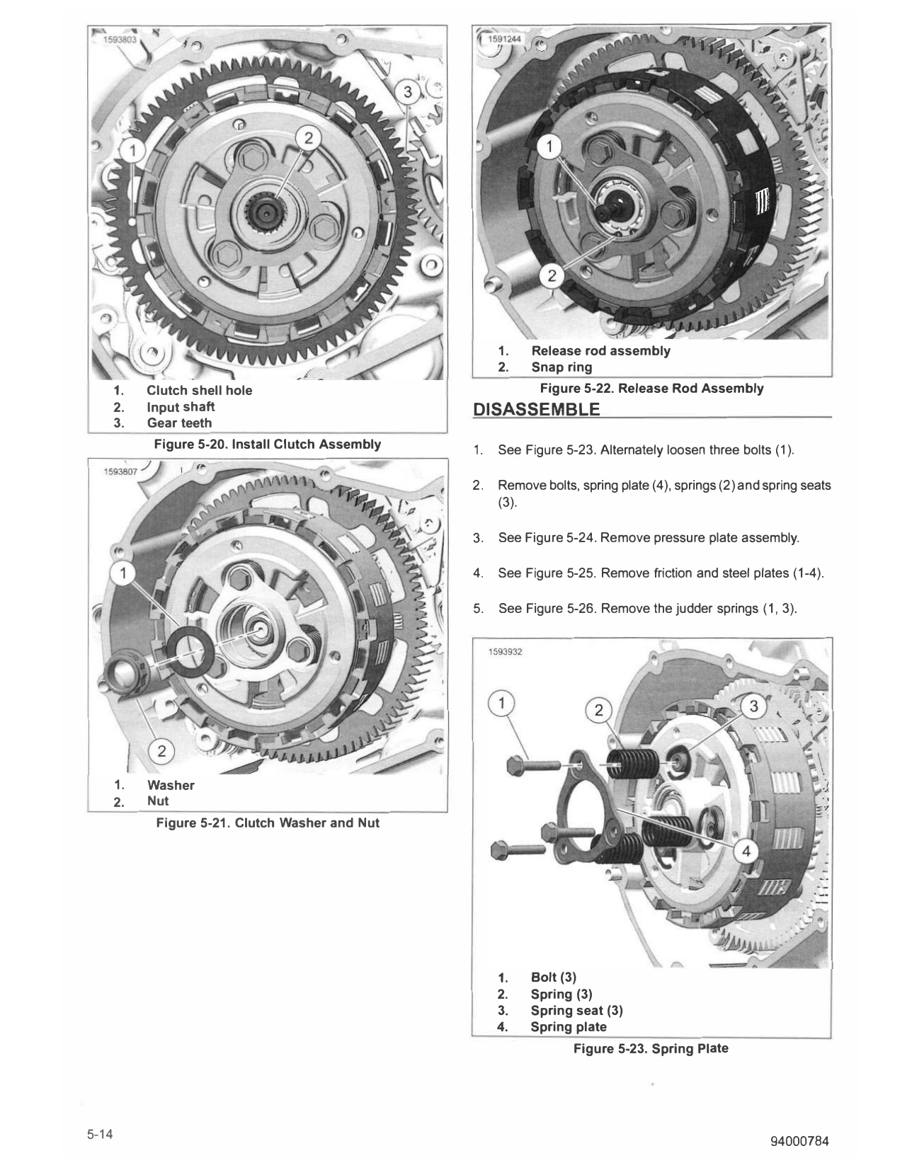
4. See Figure 5-17. Insert a suitable awl or screwdriver into
the clutch shell hole (1).
5. Pry up on the tool to release spring tension.
6. Capture the front washer (2).
7. Pull the clutch assembly (3) outward, as you pull slide your
hands behind the shell.
8. Capture the clutch bearing and spacer.
9. Remove clutch assembly.
5-12 94000784
1. Clutch shell hole Figure 5-18. Install Washer
2. Front washer
3. Clutch assembly
Figure 5-17. Clutch Removal
INSTALL
FASTENER TORQUE VALUE
Clutch nut 125-140 ft-lbs 170-190 N·m
1. See Figure 5-18. Install big washer on input shaft.
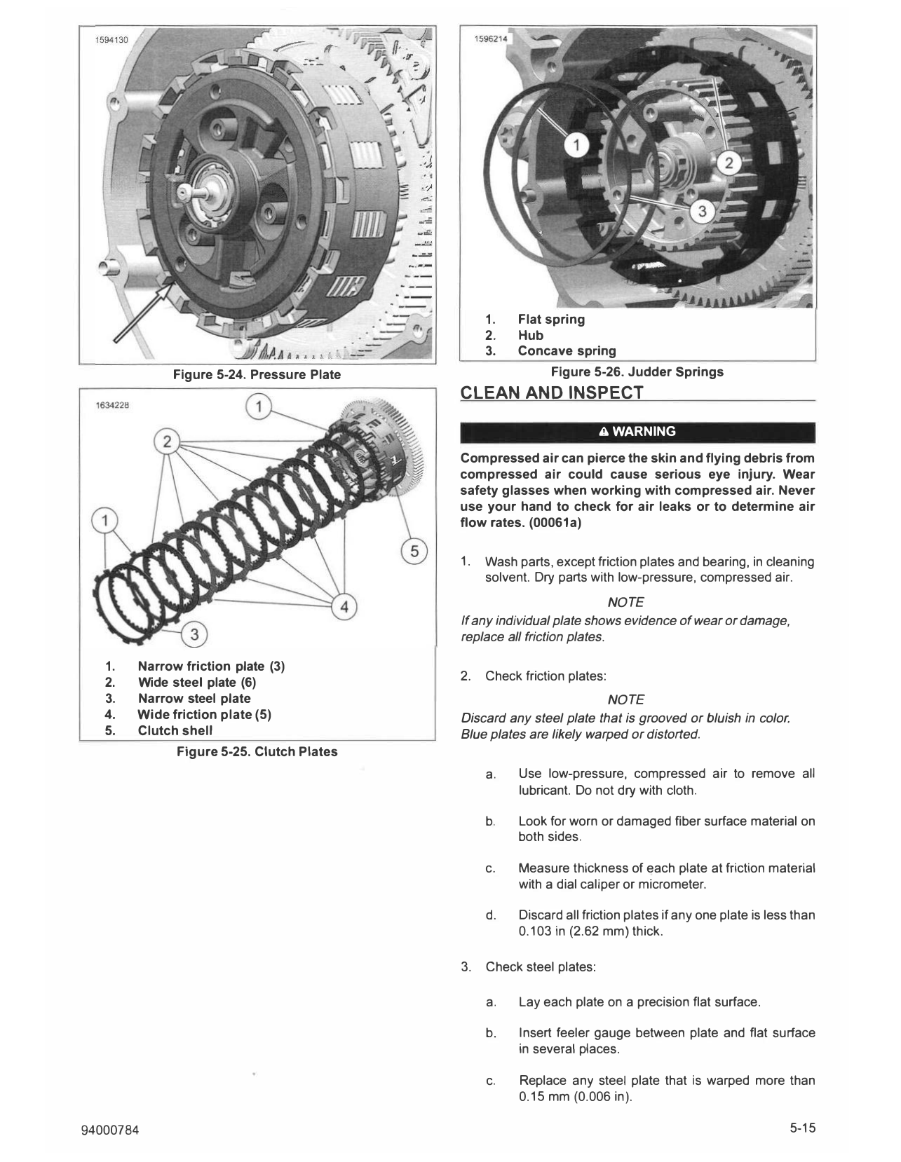
2. See Figure 5-19. Apply engine oil to needle bearings (1)
and inner bushing (2).
3. Install into clutch basket (3).
1. Needle bearings
4. See Figure 5-20. Keep inner bushing and bearing 2. Inner bushing
assembly together, install clutch basket and bearings onto 3. Clutch basket
input shaft (2). Figure 5-19. Clutch Basket Bushing and Bearings
5. Using suitable awl or screwdriver apply pressure to the
spring through clutch shell hole (1) and align teeth (3).
6. Slide assembly onto shaft aligning teeth with crankshaft
gear.
NOTE
Verify clutch scissor gear is flush with crankshaft gear.
7. See Figure 5-21. With paint mark facing out, install washer
(1).
8. Install new nut (2) using 12 point 24m socket. Tighten.
Torque: 125-140 ft-lbs (170-190 N·m) Clutch nut
9. See Figure 5-22. Install release rod assembly and bearing
(1).
10. With paint mark or beveled side out, install snap ring (2).
- ,,,,
1. Release rod assembly
2. Snap ring
1. Clutch shell hole Figure 5-22. Release Rod Assembly
2. Input shaft DISASSEMBLE
3. Gear teeth
Figure 5-20. Install Clutch Assembly 1. See Figure 5-23. Alternately loosen three bolts (1 ).
2. Remove bolts, spring plate (4), springs (2) and spring seats
(3).
3. See Figure 5-24. Remove pressure plate assembly.
4. See Figure 5-25. Remove friction and steel plates (1-4).
5. See Figure 5-26. Remove the judder springs (1, 3).
1. Washer
2. Nut
Figure 5-21. Clutch Washer and Nut
1. Bolt (3)
2. Spring (3)
3. Spring seat (3)
4. Spring plate
Figure 5-23. Spring Plate
5-14 94000784
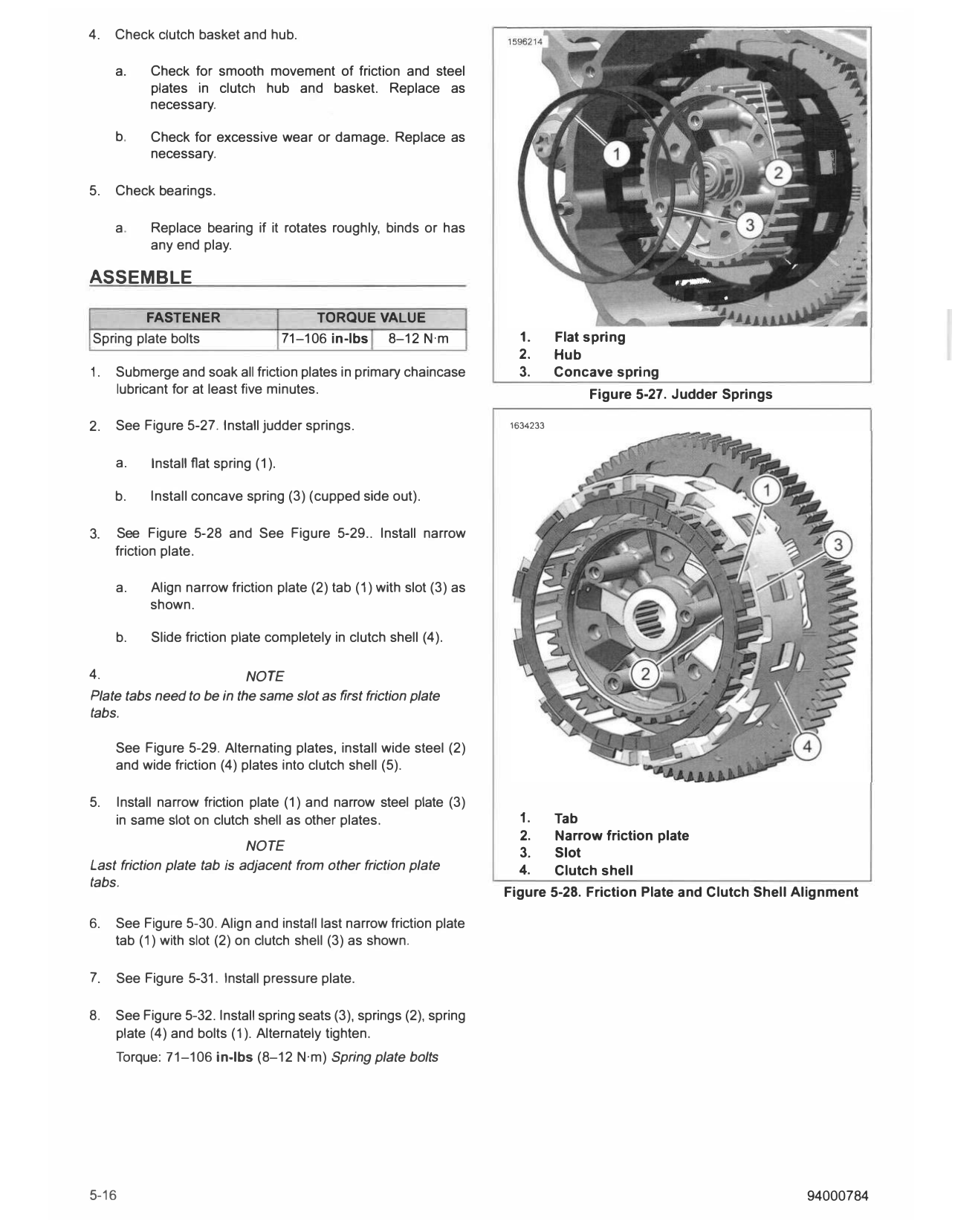
1. Flat spring
2. Hub
3. Concave spring
Figure 5-24. Pressure Plate Figure 5-26. Judder Springs
CLEAN AND INSPECT
A WARNING
Compressed air can pierce the skin and flying debris from
compressed air could cause serious eye injury. Wear
safety glasses when working with compressed air. Never
use your hand to check for air leaks or to determine air
flow rates. (00061a)
1. Wash parts, except friction plates and bearing, in cleaning
solvent. Dry parts with low-pressure, compressed air.
NOTE
If any individual plate shows evidence of wear or damage,
replace all friction plates.
1. Narrow friction plate (3)
2. Check friction plates:
2. Wide steel plate (6)
3. Narrow steel plate NOTE
4. Wide friction plate (5) Discard any steel plate that is grooved or bluish in color.
5. Clutch shell Blue plates are likely warped or distorted.
Figure 5-25. Clutch Plates
a. Use low-pressure, compressed air to remove all
lubricant. Do not dry with cloth.
b. Look for worn or damaged fiber surface material on
both sides.
c. Measure thickness of each plate at friction material
with a dial caliper or micrometer.
d. Discard all friction plates if any one plate is less than
0.103 in (2.62 mm) thick.
3. Check steel plates:
a. Lay each plate on a precision flat surface.
b. Insert feeler gauge between plate and flat surface
in several places.
c. Replace any steel plate that is warped more than
0.15 mm (0.006 in).
94000784 5-15
4. Check clutch basket and hub.
a. Check for smooth movement of friction and steel
plates in clutch hub and basket. Replace as
necessary.
b. Check for excessive wear or damage. Replace as
necessary.
5. Check bearings.
a. Replace bearing if it rotates roughly, binds or has
any end play.
ASSEMBLE
FASTENER TORQUE VALUE
Spring plate bolts 71-106 in-lbs 8-12 N·m 1. Flat spring
2. Hub
1. Submerge and soak all friction plates in primary chaincase 3. Concave spring
lubricant for at least five minutes. Figure 5-27. Judder Springs
2. See Figure 5-27. Install judder springs. 1634233
a. Install flat spring (1).
b. Install concave spring (3) (cupped side out).
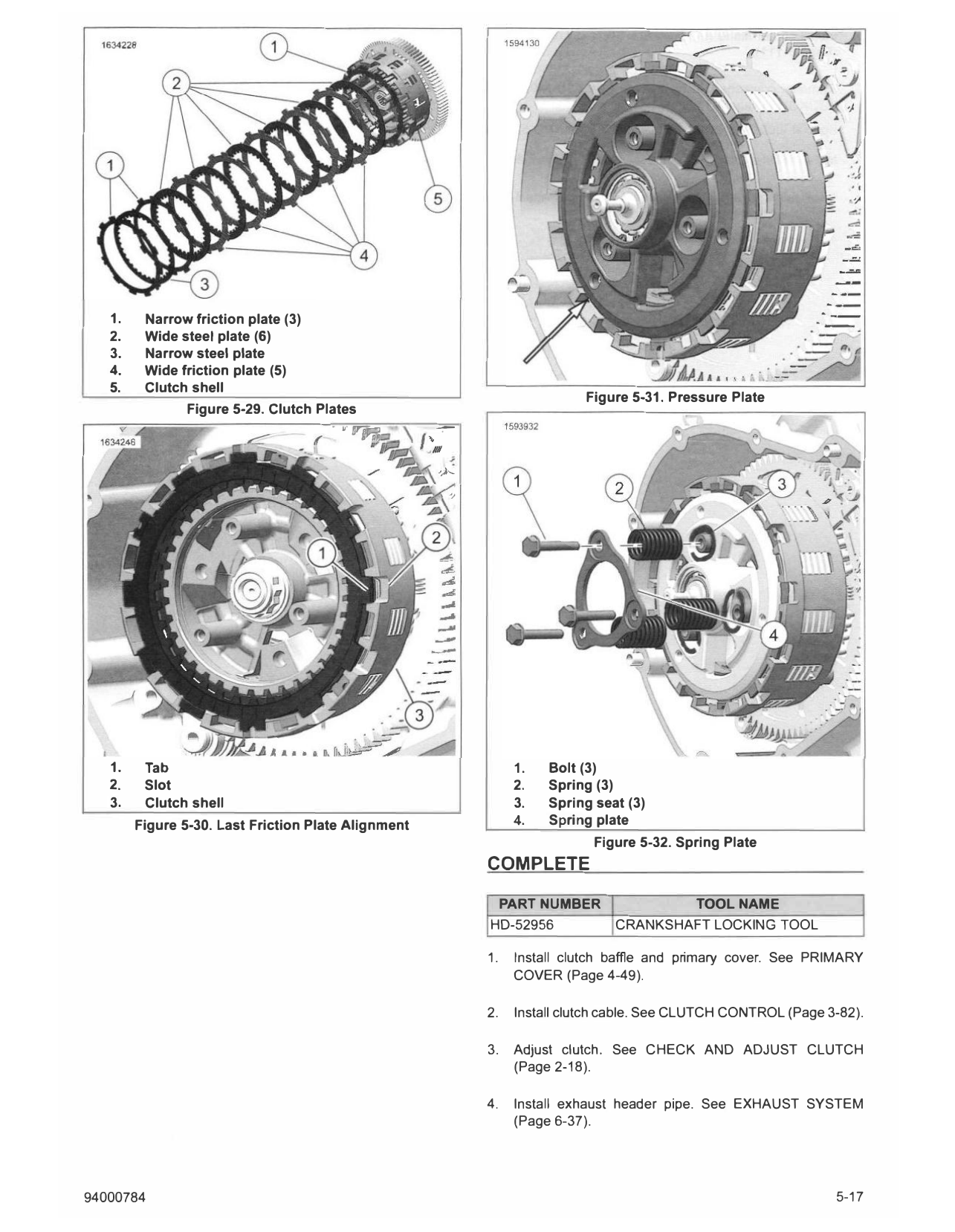
3. See Figure 5-28 and See Figure 5-29.. Install narrow
friction plate.
a. Align narrow friction plate (2) tab (1) with slot (3) as
shown.
b. Slide friction plate completely in clutch shell (4).
4. NOTE
Plate tabs need to be in the same slot as first friction plate
tabs.
See Figure 5-29. Alternating plates, install wide steel (2)
and wide friction (4) plates into clutch shell (5).
5. Install narrow friction plate (1) and narrow steel plate (3)
in same slot on clutch shell as other plates. 1. Tab
2. Narrow friction plate
NOTE 3. Slot
Last friction plate tab is adjacent from other friction plate 4. Clutch shell
tabs.
Figure 5-28. Friction Plate and Clutch Shell Alignment
6. See Figure 5-30. Align and install last narrow friction plate
tab (1) with slot (2) on clutch shell (3) as shown.
7. See Figure 5-31. Install pressure plate.
8. See Figure 5-32. Install spring seats (3), springs (2), spring
plate (4) and bolts (1 ). Alternately tighten.
Torque: 71-106 in-lbs (8-12 N·m) Spring plate bolts
5-16 94000784
1. Narrow friction plate (3)
2. Wide steel plate (6)
3. Narrow steel plate
4. Wide friction plate (5)
5. Clutch shell
Figure 5-31. Pressure Plate
Figure 5-29. Clutch Plates
- •• ,,-JP,;, ... �.-
////
,)-...
,,
1. Tab 1. Bolt (3)
2. Slot 2. Spring (3)
3. Clutch shell 3. Spring seat (3)
Figure 5-30. Last Friction Plate Alignment 4. Spring plate
Figure 5-32. Spring Plate
COMPLETE
PART NUMBER TOOL NAME
HD-52956 CRANKSHAFT LOCKING TOOL
1. Install clutch baffle and primary cover. See PRIMARY
COVER (Page 4-49).
2. Install clutch cable. See CLUTCH CONTROL (Page 3-82).
3. Adjust clutch. See CHECK AND ADJUST CLUTCH
(Page 2-18).
4. Install exhaust header pipe. See EXHAUST SYSTEM
(Page 6-37).
94000784 5-17
5. Install center stand (if equipped). See CENTER STAND 9. Install engine guards. See ENGINE GUARDS (Page 3-94).
(Page 3-111).
10. Fill with engine oil. See REPLACE ENGINE OIL AND
6. Remove crankshaft locking tool. See CRANKSHAFT FILTER (Page 2-7).
LOCKOUT (Page 4-18).
Special Tool: CRANKSHAFT LOCKING TOOL (HD-52956) 11. Install skid plate. See SKID PLATE (Page 3-92).
7. Install radiator assembly. See RADIATOR (Page 7-18). 12. Install main fuse. See POWER DISCONNECT
(Page 8-4).
8. Install fairing lowers. See FAIRING LOWERS (Page 3-90).
5-18 94000784