5.5 Output Sprocket
Fragment manuala — str. 294–295
📋 Tekst do skopiowania (OCR/wyszukiwanie)
OUTPUT SPROCKET 5.5
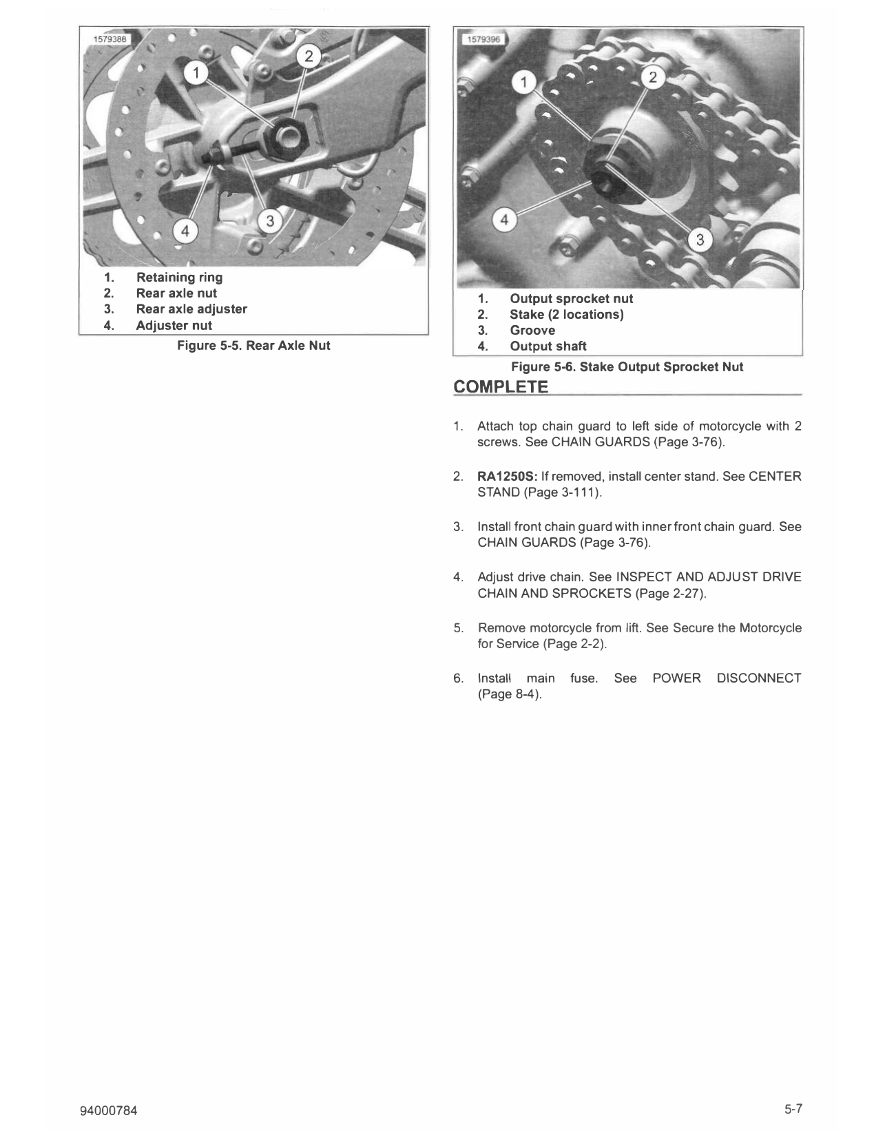
PREPARE 4. See Figure 5-6. Using a 1/8 in round flat punch, stake (2)
output sprocket nut (1) to groove (3) in output shaft (4) in
two places, 180 degrees apart.
1. Remove main fuse. See POWER DISCONNECT
(Page 8-4).
5. See Figure 5-4. Install shift control assembly (3). Secure
with 2 screws (2, 4). Tighten.
2. Position motorcycle upright on motorcycle lift. See Secure
the Motorcycle for Service (Page 2-2). Torque: 21-23 ft-lbs (28.5-31.5 N·m) Shift control
assembly screw
3. Remove front chain guard with inner front chain guard.
6. Attach shifter linkage (5) to shift rod lever (1) with screw
See CHAIN GUARDS (Page 3-76).
(6). Tighten.
4. RA1250S models: If replacing drive chain, remove center Torque: 93-106 in-lbs (10.5-12 N·m) Shift linkage to shift
stand. See CENTER STAND (Page 3-111 ). rod lever screw
5. Remove 2 screws securing top chain guard to left side of
motorcycle. See CHAIN GUARDS (Page 3-76).
REMOVE
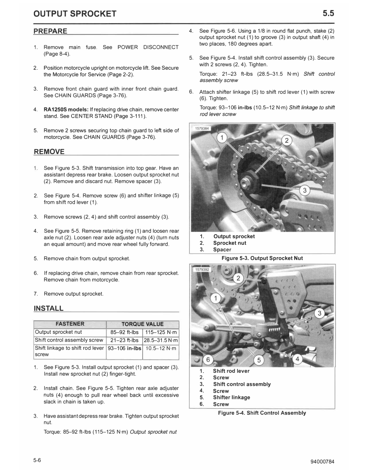
1. See Figure 5-3. Shift transmission into top gear. Have an
assistant depress rear brake. Loosen output sprocket nut
(2). Remove and discard nut. Remove spacer (3).
2. See Figure 5-4. Remove screw (6) and shifter linkage (5)
from shift rod lever (1 ).
3. Remove screws (2, 4) and shift control assembly (3).
4. See Figure 5-5. Remove retaining ring (1) and loosen rear
axle nut (2). Loosen rear axle adjuster nuts (4) (turn nuts 1. Output sprocket
an equal amount) and move rear wheel fully forward. 2. Sprocket nut
3. Spacer
5. Remove chain from output sprocket. Figure 5-3. Output Sprocket Nut
6. If replacing drive chain, remove chain from rear sprocket.
Remove chain from motorcycle.
7. Remove output sprocket.
INSTALL
FASTENER TORQUE VALUE
Output sprocket nut 85-92 ft-lbs 115-125 N·m
Shift control assembly screw 21-23 ft-lbs 28.5-31.5 N·m
Shift linkage to shift rod lever 93-106 in-lbs 10.5-12 N·m
screw
1. See Figure 5-3. Install output sprocket (1) and spacer (3).
1. Shift rod lever
Install new sprocket nut (2) finger-tight.
2. Screw
3. Shift control assembly
2. Install chain. See Figure 5-5. Tighten rear axle adjuster 4. Screw
nuts (4) enough to pull rear wheel back until excessive 5. Shifter linkage
slack in chain is taken up. 6. Screw
Figure 5-4. Shift Control Assembly
3. Have assistant depress rear brake. Tighten output sprocket
nut.
Torque: 85-92 ft-lbs (115-125 N·m) Output sprocket nut
5-6 94000784
1. Retaining ring
2. Rear axle nut 1. Output sprocket nut
3. Rear axle adjuster 2. Stake (2 locations)
4. Adjuster nut 3. Groove
Figure 5-5. Rear Axle Nut 4. Output shaft
Figure 5-6. Stake Output Sprocket Nut
COMPLETE
1. Attach top chain guard to left side of motorcycle with 2
screws. See CHAIN GUARDS (Page 3-76).
2. RA1250S: If removed, install center stand. See CENTER
STAND (Page 3-111).
3. Install front chain guard with inner front chain guard. See
CHAIN GUARDS (Page 3-76).
4. Adjust drive chain. See INSPECT AND ADJUST DRIVE
CHAIN AND SPROCKETS (Page 2-27).
5. Remove motorcycle from lift. See Secure the Motorcycle
for Service (Page 2-2).
6. Install main fuse. See POWER DISCONNECT
(Page 8-4).
94000784 5-7