4.3 Engine Oil Flow
Fragment manuala — str. 210–211
📋 Tekst do skopiowania (OCR/wyszukiwanie)
ENGINE OIL FLOW 4.3
OPERATION 7. At the end of the lower engine feed passages is the oil
pressure sensor and the oil passages leading up to each
The lubrication system is considered a semi-dry system. This of the cylinder heads. The passages lead up to the left
means it uses scavenge pumps to return oil to a specific part side of the cylinder heads feeding oil to the hydraulic lash
of the sump. Three scavenge pumps, with separate inlets, adjusters (HLA), chain tensioner, and the camshaft bearing
remove excess oil from different areas of the engine with feed grooves.
rotating parts minimizing components passing through settling
oil. This system provides optimum lubrication and oil pressure • HLA use oil pressure to adjust the valve lash.
to critical components while minimizing oil aeration. • Chain tensioner uses oil pressure to adjust the camshaft
timing chains tension.
Oil Distribution
• Feed grooves are machined into the cylinder head bearings.
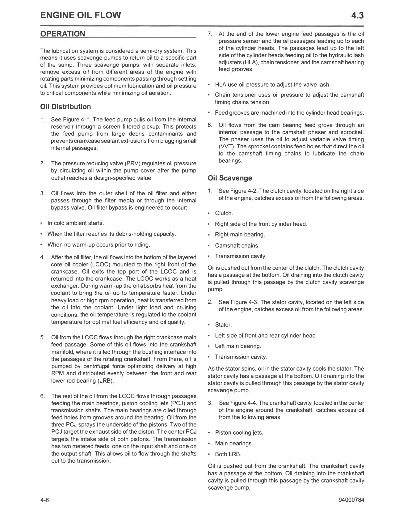
1. See Figure 4-1. The feed pump pulls oil from the internal
reservoir through a screen filtered pickup. This protects 8. Oil flows from the cam bearing feed grove through an
the feed pump from large debris contaminants and internal passage to the camshaft phaser and sprocket.
prevents crankcase sealant extrusions from plugging small The phaser uses the oil to adjust variable valve timing
internal passages. (VVT). The sprocket contains feed holes that direct the oil
to the camshaft timing chains to lubricate the chain
2. The pressure reducing valve (PRV) regulates oil pressure bearings.
by circulating oil within the pump cover after the pump
outlet reaches a design-specified value. Oil Scavenge
3. Oil flows into the outer shell of the oil filter and either 1. See Figure 4-2. The clutch cavity, located on the right side
passes through the filter media or through the internal of the engine, catches excess oil from the following areas.
bypass valve. Oil filter bypass is engineered to occur:
• Clutch.
• In cold ambient starts. • Right side of the front cylinder head.
• When the filter reaches its debris-holding capacity. Right main bearing.
• When no warm-up occurs prior to riding. • Camshaft chains.
4. After the oil filter, the oil flows into the bottom of the layered • Transmission cavity.
core oil cooler (LCOC) mounted to the right front of the
Oil is pushed out from the center of the clutch. The clutch cavity
crankcase. Oil exits the top port of the LCOC and is
has a passage at the bottom. Oil draining into the clutch cavity
returned into the crankcase. The LCOC works as a heat
is pulled through this passage by the clutch cavity scavenge
exchanger. During warm-up the oil absorbs heat from the
pump.
coolant to bring the oil up to temperature faster. Under
heavy load or high rpm operation, heat is transferred from 2. See Figure 4-3. The stator cavity, located on the left side
the oil into the coolant. Under light load and cruising of the engine, catches excess oil from the following areas.
conditions, the oil temperature is regulated to the coolant
temperature for optimal fuel efficiency and oil quality. • Stator.
5. Oil from the LCOC flows through the right crankcase main • Left side of front and rear cylinder head
feed passage. Some of this oil flows into the crankshaft • Left main bearing.
manifold, where it is fed through the bushing interface into
the passages of the rotating crankshaft. From there, oil is • Transmission cavity.
pumped by centrifugal force optimizing delivery at high As the stator spins, oil in the stator cavity cools the stator. The
RPM and distributed evenly between the front and rear stator cavity has a passage at the bottom. Oil draining into the
lower rod bearing (LRB). stator cavity is pulled through this passage by the stator cavity
scavenge pump.
6. The rest of the oil from the LCOC flows through passages
feeding the main bearings, piston cooling jets (PCJ) and 3. See Figure 4-4. The crankshaft cavity, located in the center
transmission shafts. The main bearings are oiled through of the engine around the crankshaft, catches excess oil
feed holes from grooves around the bearing. Oil from the from the following areas.
three PCJ sprays the underside of the pistons. Two of the
PCJ target the exhaust side of the piston. The center PCJ • Piston cooling jets.
targets the intake side of both pistons. The transmission
has two metered feeds, one on the input shaft and one on • Main bearings.
the output shaft. This allows oil to flow through the shafts • Both LRB.
out to the transmission.
Oil is pushed out from the crankshaft. The crankshaft cavity
has a passage at the bottom. Oil draining into the crankshaft
cavity is pulled through this passage by the crankshaft cavity
scavenge pump.
4-6 94000784
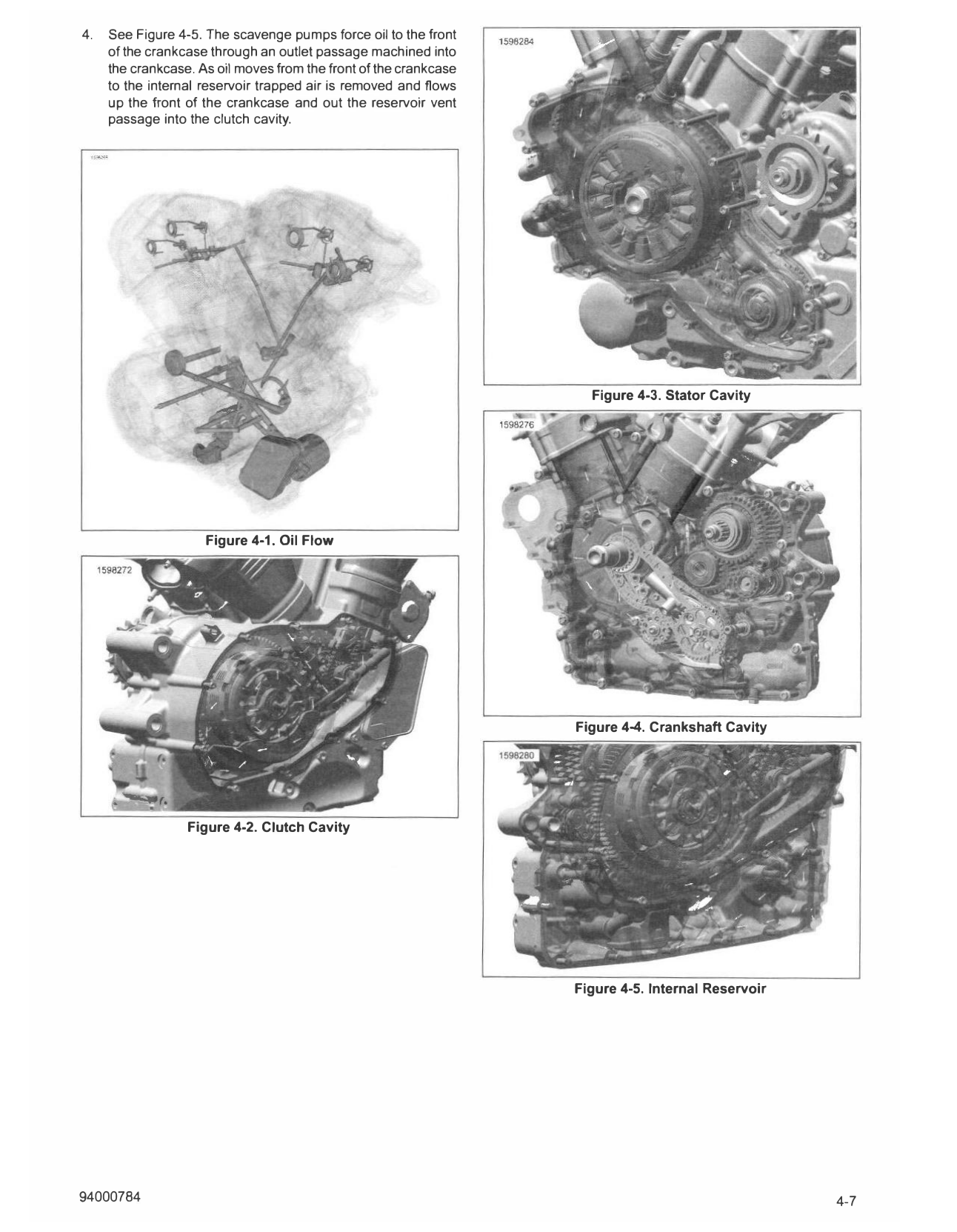
4. See Figure 4-5. The scavenge pumps force oil to the front
of the crankcase through an outlet passage machined into
the crankcase. As oil moves from the front of the crankcase
to the internal reservoir trapped air is removed and flows
up the front of the crankcase and out the reservoir vent
passage into the clutch cavity.
Figure 4-3. Stator Cavity
Figure 4-1. Oil Flow
Figure 4-4. Crankshaft Cavity
Figure 4-2. Clutch Cavity
Figure 4-5. Internal Reservoir
94000784 4-7