4.4 Oil Pump Operation
Fragment manuala — str. 212
📋 Tekst do skopiowania (OCR/wyszukiwanie)
OIL PUMP OPERATION 4.4
GENERAL
See Figure 4-6. The oil pump has four crankshaft driven gerotor
gear sets.
• The feed gerotor set distributes engine oil.
• The three scavenge gerotor sets draw oil from the clutch
cavity, stator cavity and crankshaft cavity to the lower
crankcase for the feed pump. The system directs oil through
sections of the crankcase, which minimizes aeration, before
entering the storage section.
Each gerotor gear set has an inner and outer gerotor. The inner
and outer gerotors have fixed centers that are slightly offset to
one another. The inner gerotor has one less tooth.
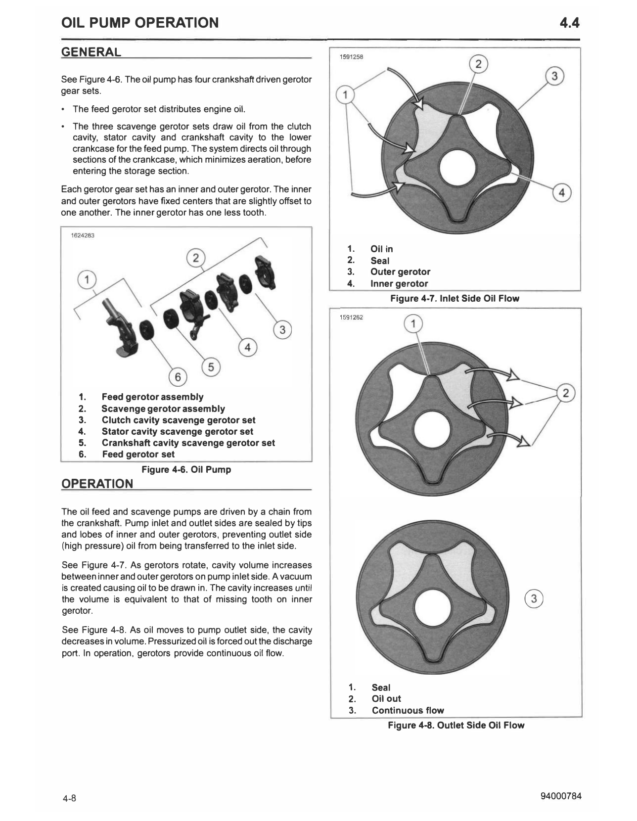
1. Oil in
2. Seal
3. Outer gerotor
4. Inner gerotor
Figure 4-7. Inlet Side Oil Flow
1. Feed gerotor assembly
2. Scavenge gerotor assembly
3. Clutch cavity scavenge gerotor set
4. Stator cavity scavenge gerotor set
5. Crankshaft cavity scavenge gerotor set
6. Feed gerotor set
Figure 4-6. Oil Pump
OPERATION
The oil feed and scavenge pumps are driven by a chain from
the crankshaft. Pump inlet and outlet sides are sealed by tips
and lobes of inner and outer gerotors, preventing outlet side
(high pressure) oil from being transferred to the inlet side.
See Figure 4-7. As gerotors rotate, cavity volume increases
between inner and outer gerotors on pump inlet side. A vacuum
0
is created causing oil to be drawn in. The cavity increases until
the volume is equivalent to that of missing tooth on inner
gerotor.
See Figure 4-8. As oil moves to pump outlet side, the cavity
decreases in volume. Pressurized oil is forced out the discharge
port. In operation, gerotors provide continuous oil flow.
1. Seal
2. Oil out
3. Continuous flow
Figure 4-8. Outlet Side Oil Flow
4-8 94000784