4.2 Specifications
Fragment manuala — str. 207–209
📋 Tekst do skopiowania (OCR/wyszukiwanie)
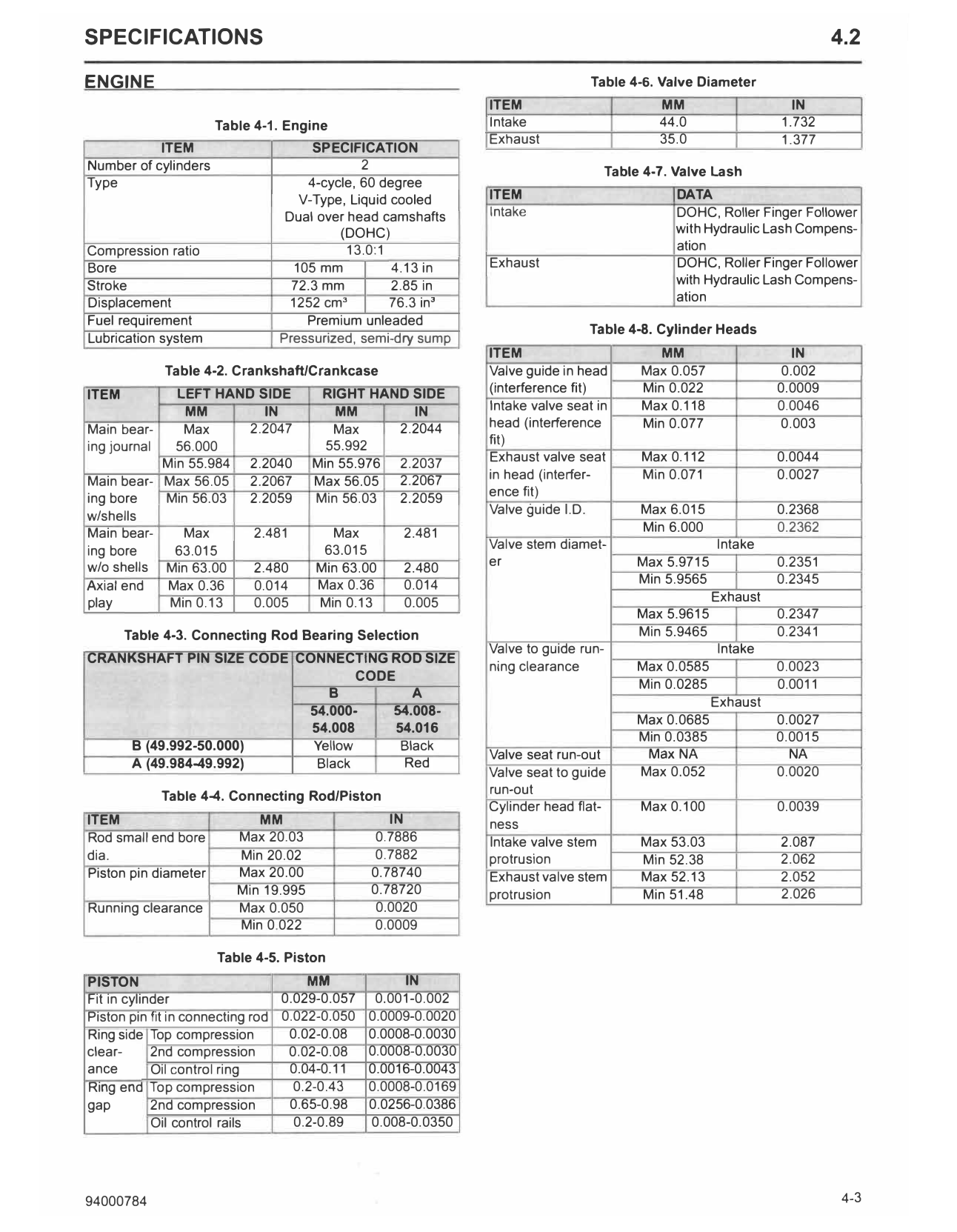
SPECIFICATIONS 4.2
ENGINE Table 4-6. Valve Diameter
ITEM MM IN
Table 4-1. Engine Intake 44.0 1.732
Exhaust 35.0 1.377
ITEM SPECIFICATION
Number of cylinders 2 Table 4-7. Valve Lash
Type 4-cycle, 60 degree
V-Type, Liquid cooled ITEM DATA
Dual over head camshafts Intake DOHC, Roller Finger Follower
(DOHC) with Hydraulic Lash Compens-
Compression ratio 13.0:1 ation
Bore 105 mm 4.13 in Exhaust DOHC, Roller Finger Follower
Stroke 72.3 mm 2.85 in with Hydraulic Lash Compens-
Displacement 1252 cm3 76.3 in3 ation
Fuel requirement Premium unleaded
Table 4-8. Cylinder Heads
Lubrication system Pressurized, semi-dry sump
ITEM MM IN
Table 4-2. Crankshaft/Crankcase Valve guide in head Max 0.057 0.002
ITEM LEFT HAND SIDE RIGHT HAND SIDE (interference fit) Min 0.022 0.0009
MM IN MM IN Intake valve seat in Max 0.118 0.0046
Main bear- Max 2.2047 Max 2.2044 head (interference Min 0.077 0.003
ing journal 56.000 55.992 fit)
Min 55.984 2.2040 Min 55.976 2.2037 Exhaust valve seat Max 0.112 0.0044
Main bear- Max 56.05 2.2067 Max 56.05 2.2067 in head (interfer- Min 0.071 0.0027
ence fit)
ing bore Min 56.03 2.2059 Min 56.03 2.2059
w/shells Valve guide I.D. Max 6.015 0.2368
Main bear- Max 2.481 Max 2.481 Min 6.000 0.2362
ing bore 63.015 63.015 Valve stem diamet- Intake
w/o shells Min 63.00 2.480 Min 63.00 2.480 er Max 5.9715 0.2351
Axial end Max 0.36 0.014 Max 0.36 0.014 Min 5.9565 0.2345
play Min 0.13 0.005 Min 0.13 0.005 Exhaust
Max 5.9615 0.2347
Table 4-3. Connecting Rod Bearing Selection Min 5.9465 0.2341
Valve to guide run- Intake
CRANKSHAFT PIN SIZE CODE CONNECTING ROD SIZE
ning clearance Max 0.0585 0.0023
CODE
Min 0.0285 0.0011
8 A
Exhaust
54.000- 54.008-
Max 0.0685 0.0027
54.008 54.016
Min 0.0385 0.0015
8 (49.992-50.000) Yellow Black
Valve seat run-out Max NA NA
A (49.984-49.992) Black Red
Valve seat to guide Max 0.052 0.0020
Table 4-4. Connecting Rod/Piston run-out
Cylinder head flat- Max 0.100 0.0039
ITEM MM IN ness
Rod small end bore Max 20.03 0.7886 Intake valve stem Max 53.03 2.087
dia. Min 20.02 0.7882 protrusion Min 52.38 2.062
Piston pin diameter Max 20.00 0.78740 Exhaust valve stem Max 52.13 2.052
Min 19.995 0.78720 protrusion Min 51.48 2.026
Running clearance Max 0.050 0.0020
Min 0.022 0.0009
Table 4-5. Piston
PISTON MM IN
Fit in cylinder 0.029-0.057 0.001-0.002
Piston pin fit in connecting rod 0.022-0.050 0.0009-0.0020
Ring side Top compression 0.02-0.08 0.0008-0.0030
clear- 2nd compression 0.02-0.08 0.0008-0.0030
ance Oil control ring 0.04-0.11 0.0016-0.0043
Ring end Top compression 0.2-0.43 0.0008-0.0169
gap 2nd compression 0.65-0.98 0.0256-0.0386
Oil control rails 0.2-0.89 0.008-0.0350
94000784 4-3
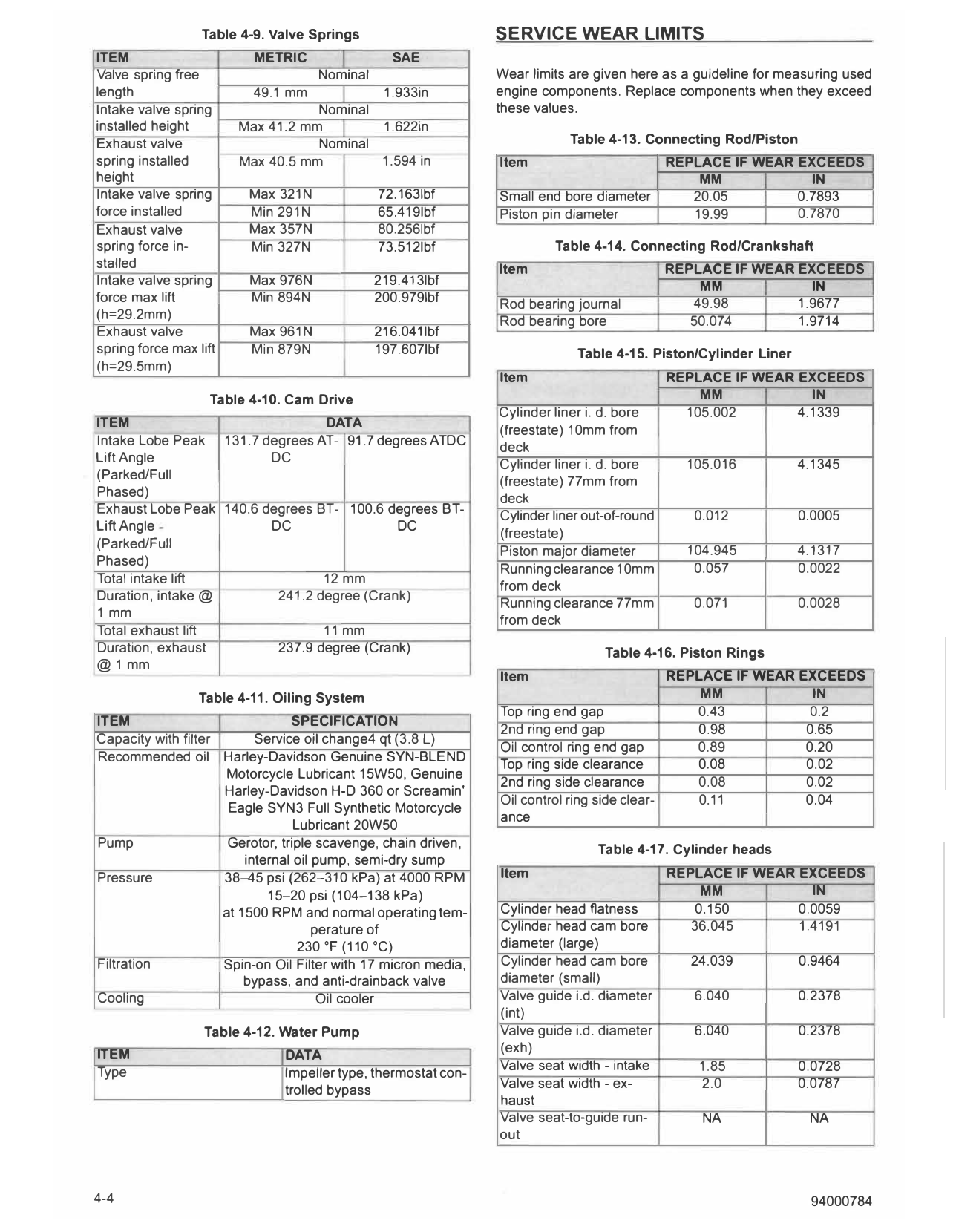
Table 4-9. Valve Springs SERVICE WEAR LIMITS
ITEM METRIC SAE
Valve spring free Nominal Wear limits are given here as a guideline for measuring used
length 49.1 mm 1.933in engine components. Replace components when they exceed
Intake valve spring Nominal these values.
installed height Max 41.2 mm 1.622in
Exhaust valve Nominal Table 4-13. Connecting Rod/Piston
spring installed Max 40.5 mm 1.594 in Item REPLACE IF WEAR EXCEEDS
height MM IN
Intake valve spring Max 321N 72.163Ibf Small end bore diameter 20.05 0.7893
force installed Min 291N 65.419Ibf Piston pin diameter 19.99 0.7870
Exhaust valve Max 357N 80.256Ibf
spring force in- Min 327N 73.512Ibf Table 4-14. Connecting Rod/Crankshaft
stalled Item REPLACE IF WEAR EXCEEDS
Intake valve spring Max 976N 219.413Ibf MM IN
force max lift Min 894N 200.979Ibf Rod bearing journal 49.98 1.9677
(h=29.2mm) Rod bearing bore 50.074 1.9714
Exhaust valve Max 961N 216.041 lbf
spring force max lift Min 879N 197.607Ibf Table 4-15. Piston/Cylinder Liner
(h=29.5mm)
Item REPLACE IF WEAR EXCEEDS
Table 4-10. Cam Drive MM IN
Cylinder liner i. d. bore 105.002 4.1339
ITEM DATA
(freestate) 10mm from
Intake Lobe Peak 131.7 degrees AT- 91.7 degrees ATDC deck
Lift Angle DC 105.016 4.1345
Cylinder liner i. d. bore
(Parked/Full (freestate) 77mm from
Phased)
deck
Exhaust Lobe Peak 140.6 degrees BT- 100.6 degrees BT- Cylinder liner out-of-round 0.012 0.0005
Lift Angle DC DC
(freestate)
(Parked/Full
Piston major diameter 104.945 4.1317
Phased)
Running clearance 10mm 0.057 0.0022
Total intake lift 12 mm
from deck
Duration, intake@ 241 .2 degree (Crank)
Running clearance 77mm 0.071 0.0028
1 mm
from deck
Total exhaust lift 11 mm
Duration, exhaust 237.9 degree (Crank) Table 4-16. Piston Rings
@1 mm
Item REPLACE IF WEAR EXCEEDS
Table 4-11. Oiling System MM IN
Top ring end gap 0.43 0.2
ITEM SPECIFICATION
2nd ring end gap 0.98 0.65
Capacity with filter Service oil change4 qt (3.8 L)
Oil control ring end gap 0.89 0.20
Recommended oil Harley-Davidson Genuine SYN-BLEND
Top ring side clearance 0.08 0.02
Motorcycle Lubricant 15W50, Genuine
2nd ring side clearance 0.08 0.02
Harley-Davidson H-D 360 or Screamin'
Oil control ring side clear- 0.11 0.04
Eagle SYN3 Full Synthetic Motorcycle
ance
Lubricant 20W50
Pump Gerotor, triple scavenge, chain driven, Table 4-17. Cylinder heads
internal oil pump, semi-dry sump
Pressure 38-45 psi (262-310 kPa) at 4000 RPM Item REPLACE IF WEAR EXCEEDS
15--20 psi (104-138 kPa) MM IN
at 1500 RPM and normal operating tern- Cylinder head flatness 0.150 0.0059
perature of Cylinder head cam bore 36.045 1.4191
230 °F (110 °C) diameter (large)
Filtration Spin-on Oil Filter with 17 micron media, Cylinder head cam bore 24.039 0.9464
bypass, and anti-drainback valve diameter (small)
Cooling Oil cooler Valve guide i.d. diameter 6.040 0.2378
(int)
Table 4-12. Water Pump Valve guide i.d. diameter 6.040 0.2378
ITEM (exh)
DATA
Type Valve seat width - intake 1.85 0.0728
Impeller type, thermostat con-
trolled bypass Valve seat width - ex- 2.0 0.0787
haust
Valve seat-to-guide run- NA NA
out
4-4 94000784
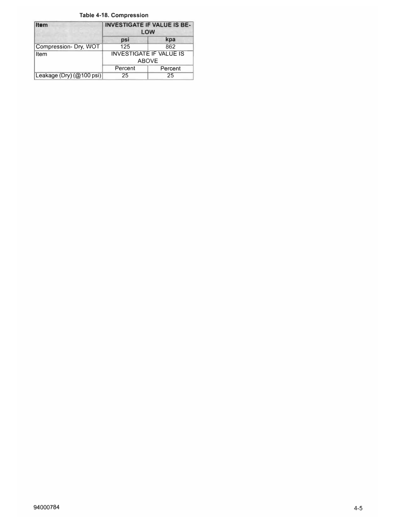
Table 4-18. Compression
Item INVESTIGATE IF VALUE IS BE-
LOW
psi I kpa
Compression- Dry, WOT
Item
125 I 862
INVESTIGATE IF VALUE IS
ABOVE
Percent I Percent
Leakage (Dry) (@100 psi) 25 I 25
94000784 4-5