4.28 Balancer
Fragment manuala — str. 279–280
📋 Tekst do skopiowania (OCR/wyszukiwanie)
BALANCER 4.28
PREPARE 22. Remove oil pump drive. See OIL PUMP DRIVE
(Page 4-57).
1. Use low-pressure compressed air to clean exterior surfaces
of engine and vehicle. a. Remove chain guides.
b. Remove balancer gear.
2. Remove main fuse. See POWER DISCONNECT
(Page 8-4).
23. Remove starter gear. See STARTER GEAR (Page 4-56).
3. Remove output sprocket. See OUTPUT SPROCKET
(Page 5-6). REMOVE
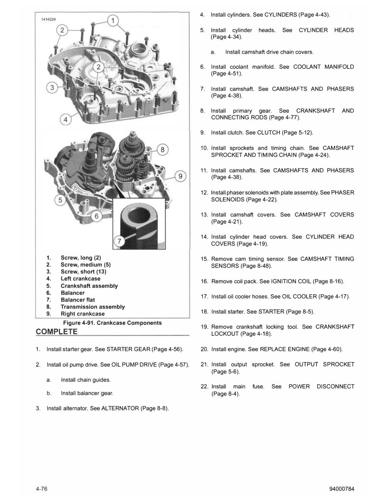
4. Remove engine. See REPLACE ENGINE (Page 4-60). 1. See Figure 4-91. Remove screws (1, 2, 3).
5. Install crankshaft locking tool. See CRANKSHAFT 2. Remove left crankcase (4).
LOCKOUT (Page 4-18).
3. Remove balancer (6).
6. Remove starter. See STARTER (Page 8-5).
4. Clean both crankcase halves from gasket material. See
7. Remove oil cooler hoses. See OIL COOLER (Page 4-17). CRANKCASE (Page 4-66).
8. Remove coil pack. See IGNITION COIL (Page 8-16). INSTALL
9. Remove cam timing sensor. See CAMSHAFT TIMING CONSUMABLE PART NUMBER
SENSORS (Page 8-48). HARLEY-DAVIDSON 99650-02
HIGH
10. Remove cylinder head covers. See CYLINDER HEAD PERFORMANCE
COVERS (Page 4-19). SEALANT - GRAY
11. Remove camshaft covers. See CAMSHAFT COVERS 1. See Figure 4-91. Install balancer (6) in right crankcase (9).
(Page 4-21).
a. Balancer flat (7) should face left crankcase (4) for
12. Remove phaser solenoids with plate assembly. See proper assembly and operation.
PHASER SOLENOIDS (Page 4-22).
2. Install left crankcase.
13. Remove camshafts. See CAMSHAFTS AND PHASERS
(Page 4-38). a. See Figure 4-78. Apply Diameter: .090 in (2 mm)
bead of sealant to right crankcase as shown.
14. Remove sprockets and timing chain. See CAMSHAFT
HARLEY-DAVIDSON HIGH PERFORMANCE
SPROCKET AND TIMING CHAIN (Page 4-24).
SEALANT - GRAY (99650-02)
15. Remove coolant manifold. See COOLANT MANIFOLD b. See Figure 4-91. Install left crankcase (4).
(Page 4-51).
3. Install screws (1, 2, 3).
16. Remove cylinder heads. See CYLINDER HEADS
(Page 4-34).
4. Tighten screws in sequence. See CRANKCASE
(Page 4-66)
a. Remove camshaft drive chain covers.
17. Remove clutch. See CLUTCH (Page 5-12).
18. Remove camshaft. See CAMSHAFTS AND PHASERS
(Page 4-38).
19. Remove primary gear. See CRANKSHAFT AND
CONNECTING RODS (Page 4-77).
20. Remove cylinders. See CYLINDERS (Page 4-43).
21. Remove alternator. See ALTERNATOR (Page 8-8).
94000784 4-75
4. Install cylinders. See CYLINDERS (Page 4-43).
5. Install cylinder heads. See CYLINDER HEADS
(Page 4-34).
a. Install camshaft drive chain covers.
6. Install coolant manifold. See COOLANT MANIFOLD
(Page 4-51).
7. Install camshaft. See CAMSHAFTS AND PHASERS
(Page 4-38).
8. Install primary gear. See CRANKSHAFT AND
CONNECTING RODS (Page 4-77).
9. Install clutch. See CLUTCH (Page 5-12).
10. Install sprockets and timing chain. See CAMSHAFT
SPROCKET AND TIMING CHAIN (Page 4-24).
11. Install camshafts. See CAMSHAFTS AND PHASERS
(Page 4-38).
12. Install phaser solenoids with plate assembly. See PHASER
SOLENOIDS (Page 4-22).
13. Install camshaft covers. See CAMSHAFT COVERS
(Page 4-21).
14. Install cylinder head covers. See CYLINDER HEAD
COVERS (Page 4-19).
1. Screw, long (2) 15. Remove cam timing sensor. See CAMSHAFT TIMING
2. Screw, medium (5) SENSORS (Page 8-48).
3. Screw, short (13)
4. Left crankcase 16. Remove coil pack. See IGNITION COIL (Page 8-16).
5. Crankshaft assembly
6. Balancer
17. Install oil cooler hoses. See OIL COOLER (Page 4-17).
7. Balancer flat
8. Transmission assembly
9. Right crankcase 18. Install starter. See STARTER (Page 8-5).
Figure 4-91. Crankcase Components
19. Remove crankshaft locking tool. See CRANKSHAFT
COMPLETE LOCKOUT (Page 4-18).
1. Install starter gear. See STARTER GEAR (Page 4-56). 20. Install engine. See REPLACE ENGINE (Page 4-60).
2. Install oil pump drive. See OIL PUMP DRIVE (Page 4-57). 21. Install output sprocket. See OUTPUT SPROCKET
(Page 5-6).
a. Install chain guides.
22. Install main fuse. See POWER DISCONNECT
b. Install balancer gear. (Page 8-4).
3. Install alternator. See ALTERNATOR (Page 8-8).
4-76 94000784