4.27 Crankcase
Fragment manuala — str. 270–278
📋 Tekst do skopiowania (OCR/wyszukiwanie)
CRANKCASE 4.27
PREPARE 21. Remove oil pump drive. See OIL PUMP DRIVE
(Page 4-57).
PART NUMBER TOOLNAME
HD-52956 CRANKSHAFT LOCKING TOOL a. Remove chain guides.
1. Use low-pressure compressed air to clean exterior surfaces b. Remove balancer gear.
of engine and vehicle.
22. Remove starter gear. See STARTER GEAR (Page 4-56).
2. Remove main fuse. See POWER DISCONNECT
(Page 8-4). 23. Remove oil pump assembly. See OIL PUMP (Page 4-59).
3. Remove output sprocket. See OUTPUT SPROCKET DISASSEMBLE
(Page 5-6).
PART NUMBER TOOLNAME
4. Remove engine. See REPLACE ENGINE (Page 4-60). HD-52957 CRANKSHAFT PROTECTOR
5. Install crankshaft locking tool. See CRANKSHAFT NOTE
LOCKOUT (Page 4-18). When setting down crankcases on a workbench, be
Special Tool: CRANKSHAFT LOCKING TOOL (HD-52956) EXTREMELY CAREFUL NOT to bend the oil nozzles. If they
are bent, the stream of oil will be misdirected and could cause
6. Remove starter. See STARTER (Page 8-5). the piston to overheat and result in catastrophic engine
damage.
7. Remove oil cooler hoses. See OIL COOLER (Page 4-17).
1. See Figure 4-77. Separate crankcase halves.
8. Remove coil pack. See IGNITION COIL (Page 8-16).
a. Remove screws (1, 2, 3).
9. Remove cam timing sensor. See CAMSHAFT TIMING
SENSORS (Page 8-48). b. Install Crankshaft protector.
Special Tool: CRANKSHAFT PROTECTOR
10. Remove cylinder head covers. See CYLINDER HEAD (HD-52957)
COVERS (Page 4-19).
c. Separate case halves.
11. Remove camshaft covers. See CAMSHAFT COVERS
d. Lift left crankcase half (4) off end of crankshaft
(Page 4-21).
assembly (5), balancer (6) and transmission
assembly (7).
12. Remove phaser solenoids with plate assembly. See
PHASER SOLENOIDS (Page 4-22).
2. Remove crankshaft assembly (5). See CRANKSHAFT
AND CONNECTING RODS (Page 4-77).
13. Remove sprockets and timing chain. See CAMSHAFT
SPROCKET AND TIMING CHAIN (Page 4-24).
3. Remove balancer (6). See BALANCER (Page 4-75).
14. Remove primary gear. See CRANKSHAFT AND
4. Remove transmission assembly (7). See TRANSMISSION
CONNECTING RODS (Page 4-77).
(Page 5-20).
15. Remove coolant manifold. See COOLANT MANIFOLD
5. Remove scavenge oil pump assembly. See SCAVENGE
(Page 4-51 ).
OIL PUMP (Page 4-80).
16. Remove cylinder heads. See CYLINDER HEADS
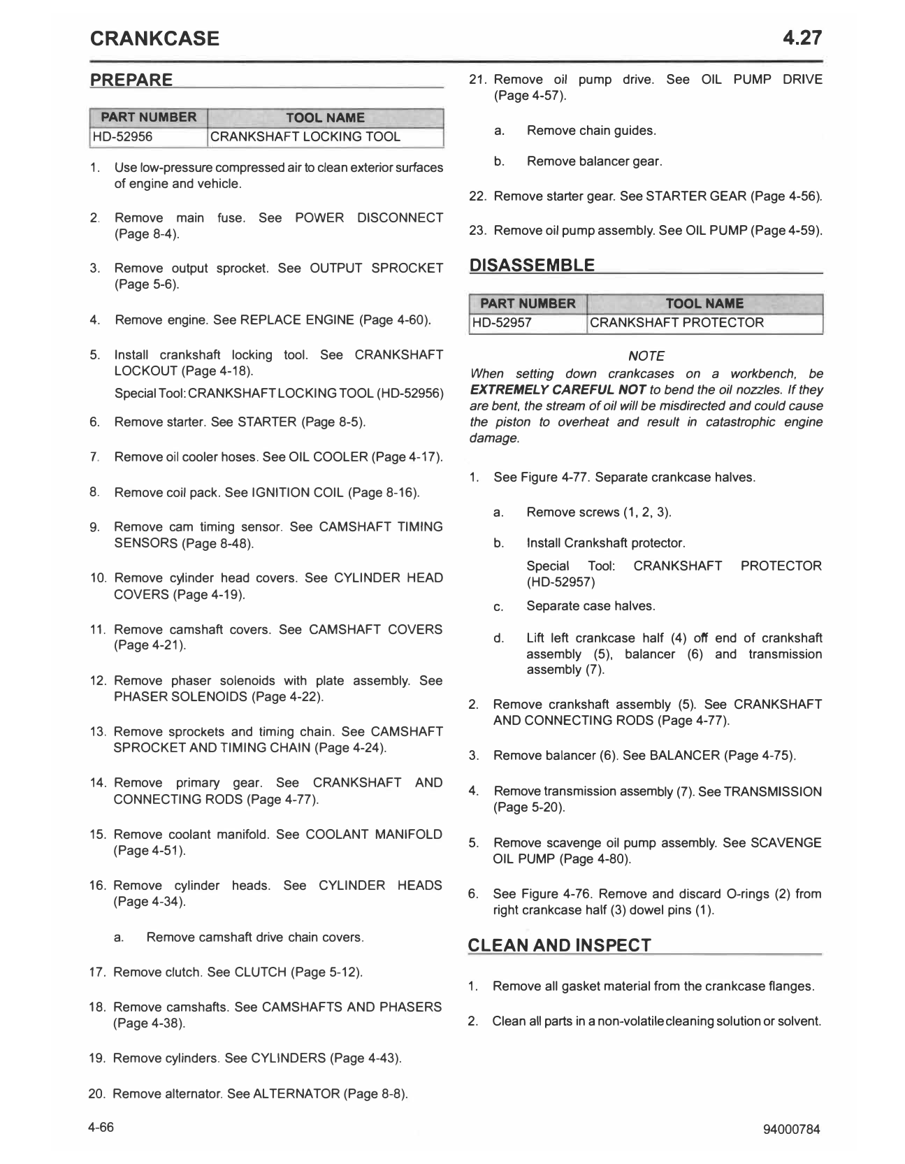
6. See Figure 4-76. Remove and discard O-rings (2) from
(Page 4-34).
right crankcase half (3) dowel pins (1).
a. Remove camshaft drive chain covers.
CLEAN AND INSPECT
17. Remove clutch. See CLUTCH (Page 5-12).
1. Remove all gasket material from the crankcase flanges.
18. Remove camshafts. See CAMSHAFTS AND PHASERS
(Page 4-38). 2. Clean all parts in a non-volatile cleaning solution or solvent.
19. Remove cylinders. See CYLINDERS (Page 4-43).
20. Remove alternator. See ALTERNATOR (Page 8-8).
4-66 94000784
A WARNING 3. Install transmission assembly (7). See TRANSMISSION
(Page 5-20).
Compressed air can pierce the skin and flying debris from
compressed air could cause serious eye injury. Wear
4. Install balancer (6). See BALANCER (Page 4-75).
safety glasses when working with compressed air. Never
use your hand to check for air leaks or to determine air NOTE
flow rates. (00061a) Lubriplate 105 or if unavailable use Screamin' Eagle
assembly lube liberally on main bearings and connecting
3. Dry parts with moisture-free compressed air. rods or bearing failure may occur.
4. Verify that all oil holes are clean and open. 5. Install crankshaft assembly (5). See CRANKSHAFT AND
CONNECTING RODS (Page 4-77).
5. Check dowel pins for looseness, wear or damage. Replace Consumable: LUBRIPLATE NO. 105 (L0034-094)
if necessary. Consumable: SCREAMIN' EAGLE ASSEMBLY LUBE
(11300002)
6. Use a file to carefully remove any nicks or burrs from
machined surfaces. 6. Install scavenge oil pump assembly. See SCAVENGE OIL
PUMP (Page 4-80).
7. Clean out tapped holes and clean up damaged threads.
7. Connect crankcase halves.
8. Check the top of the crankcase for flatness with a
straightedge and feeler gauge. Replace if warped. a. Verify that both dowel pins are installed in split line
face of right case half.
9. Spray all machined surfaces with clean engine oil.
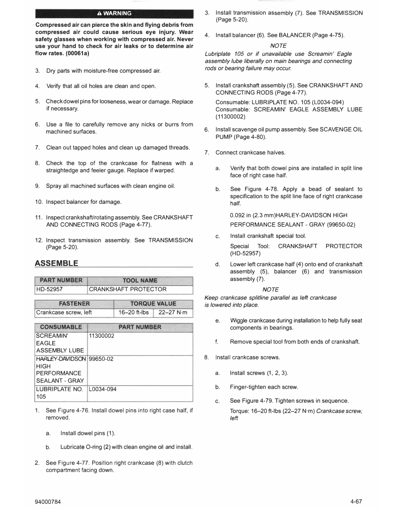
b. See Figure 4-78. Apply a bead of sealant to
specification to the split line face of right crankcase
10. Inspect balancer for damage. half.
11. Inspect crankshaft/rotating assembly. See CRANKSHAFT 0.092 in (2.3 mm)HARLEY-DAVIDSON HIGH
AND CONNECTING RODS (Page 4-77). PERFORMANCE SEALANT - GRAY (99650-02)
c. Install crankshaft special tool.
12. Inspect transmission assembly. See TRANSMISSION
(Page 5-20). Special Tool: CRANKSHAFT PROTECTOR
(HD-52957)
ASSEMBLE d. Lower left crankcase half (4) onto end of crankshaft
assembly (5), balancer (6) and transmission
PART NUMBER TOOL NAME assembly (7).
HD-52957 CRANKSHAFT PROTECTOR NOTE
Keep crankcase splitline parallel as left crankcase
FASTENER TORQUE VALUE is lowered into place.
Crankcase screw, left 16-20 ft-lbs 22-27 N·m
e. Wiggle crankcase during installation to help fully seat
CONSUMABLE PART NUMBER components in bearings.
SCREAM IN' 11300002
EAGLE f. Remove special tool from b oth ends of crankshaft.
ASSEMBLY LUBE
HARLEY-DAVIDSON 99650-02 8. Install crankcase screws.
HIGH
PERFORMANCE a. Install screws (1, 2, 3).
SEALANT - GRAY
LUBRIPLATE NO. L0034-094 b. Finger-tighten each screw.
105
c. See Figure 4-79. Tighten screws in sequence.
1. See Figure 4-76. Install dowel pins into right case half, if Torque: 16-20 ft-lbs (22-27 N·m) Crankcase screw,
removed. left
a. Install dowel pins (1).
b. Lubricate O-ring (2) with clean engine oil and install.
2. See Figure 4-77. Position right crankcase (8) with clutch
compartment facing down.
94000784 4-67
1421092 1416014 ...
Figure 4-78. Crankcase Sealant Application
1. Dowel pin (2)
2. 0-ring (2)
3. Right crankcase half
Figure 4-76. Dowel Pins
Figure 4-79. Crankcase Torque Sequence
REPAIR RIGHT CRANKCASE HALF
PART NUMBER TOOL NAME
HD-52961 MAIN BEARING INSTALLATION TOOL
FASTENER TORQUE VALUE
Screw, retainging plate, trans- 80-97 in-lbs
mission mainshaft bearing I
9-11 N·m
Main Bearing
Remove
1. Remove main bearings.
1. Screw, long (2)
2. Screw, medium (5) a. See Figure 4-80. Place main bearing
3. Screw, short (13) removal/installation tool base (2) wide end (1) up.
4. Left crankcase
5. Crankshaft assembly Special Tool: MAIN BEARING INSTALLATION TOOL
6. Balancer (HD-52961)
7. Transmission assembly b. See Figure 4-81. Place crankcase main bearing on
8. Right crankcase tool base.
Figure 4-77. Separate Crankcase Halves
4-68 94000784
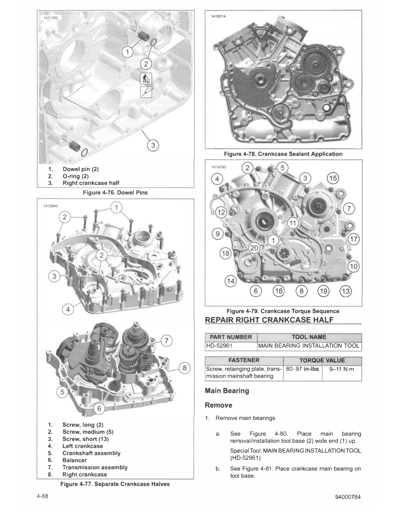
c. Install main bearing removal tool shaft as shown. 1581279
d. Press out bearings.
e. Discard bearing halves.
Install
1. Install main bearings.
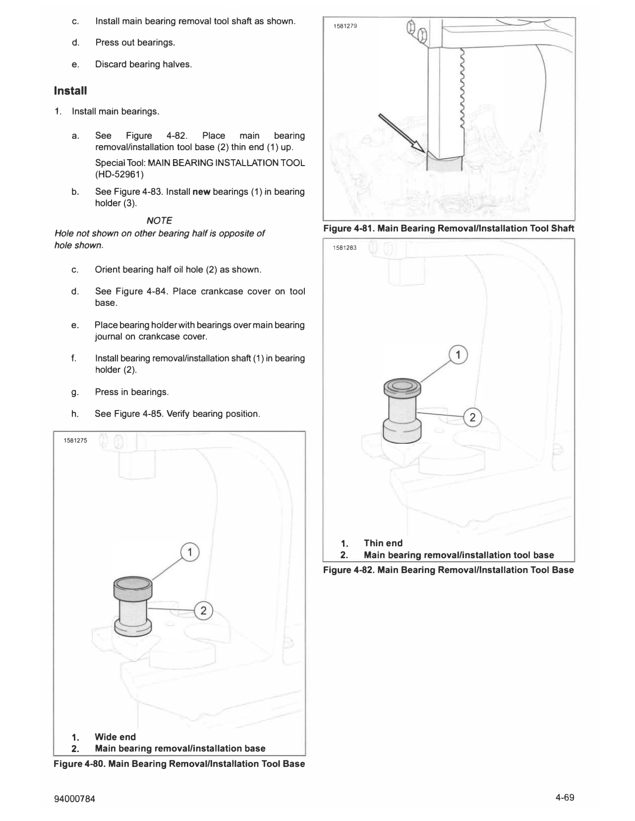
a. See Figure 4-82. Place main bearing
removal/installation tool base (2) thin end (1) up.
Special Tool: MAIN BEARING INSTALLATION TOOL
(HD-52961)
b. See Figure 4-83. Install new bearings (1) in bearing
holder (3).
NOTE
Figure 4-81. Main Bearing Removal/Installation Tool Shaft
Hole not shown on other bearing half is opposite of
hole shown. 1581283
c. Orient bearing half oil hole (2) as shown.
d. See Figure 4-84. Place crankcase cover on tool
base.
e. Place bearing holder with bearings over main bearing
journal on crankcase cover.
f. Install bearing removal/installation shaft (1) in bearing
holder (2).
g. Press in bearings.
h. See Figure 4-85. Verify bearing position.
1581275
1. Thin end
2. Main bearing removal/installation tool base
Figure 4-82. Main Bearing Removal/Installation Tool Base
1. Wide end
2. Main bearing removal/installation base
Figure 4-80. Main Bearing Removal/Installation Tool Base
94000784 4-69
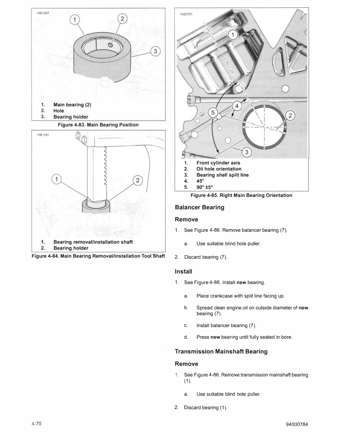
1581287
1. Main bearing (2)
2. Hole
3. Bearing holder
Figure 4-83. Main Bearing Position
1581291 �
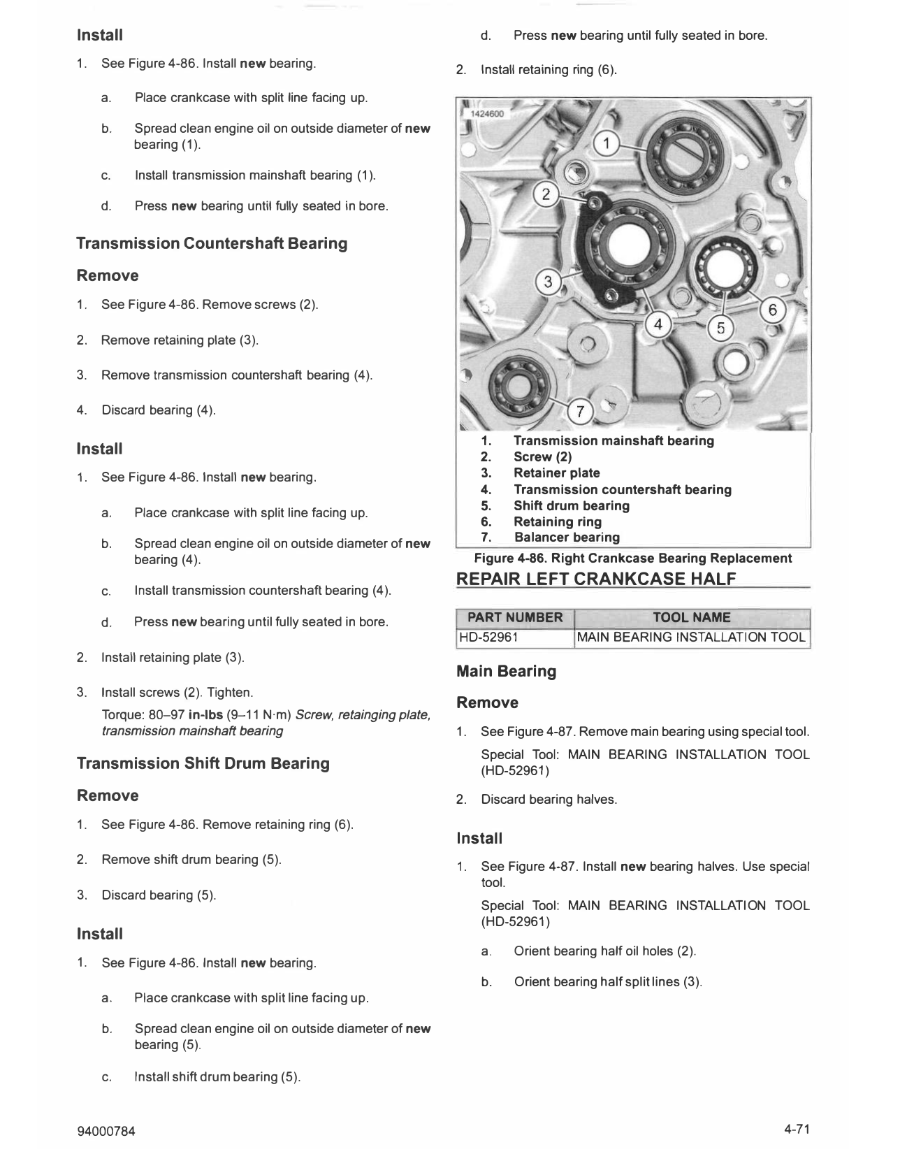
1. Front cylinder axis
2. Oil hole orientation
3. Bearing shell split line
4. 45°
5. 90° ±5°
Figure 4-85. Right Main Bearing Orientation
Balancer Bearing
Remove
1. See Figure 4-86. Remove balancer bearing (7).
1. Bearing removal/installation shaft a. Use suitable blind hole puller.
2. Bearing holder
Figure 4-84. Main Bearing Removal/Installation Tool Shaft 2. Discard bearing (7).
Install
1. See Figure 4-86. Install new bearing.
a. Place crankcase with split line facing up.
b. Spread clean engine oil on outside diameter of new
bearing (7).
c. Install balancer bearing (7).
d. Press new bearing until fully seated in bore.
Transmission Mainshaft Bearing
Remove
1. See Figure 4-86. Remove transmission mainshaft bearing
(1).
a. Use suitable blind hole puller.
2. Discard bearing (1).
4-70 94000784
Install d. Press new bearing until fully seated in bore.
1. See Figure 4-86. Install new bearing. Install retaining ring (6).
2.
a. Place crankcase with split line facing up.
b. Spread clean engine oil on outside diameter of new
bearing (1).
c. Install transmission mainshaft bearing (1).
d. Press new bearing until fully seated in bore.
Transmission Countershaft Bearing
Remove
1. See Figure 4-86. Remove screws (2).
2. Remove retaining plate (3).
3. Remove transmission countershaft bearing (4).
4. Discard bearing (4).
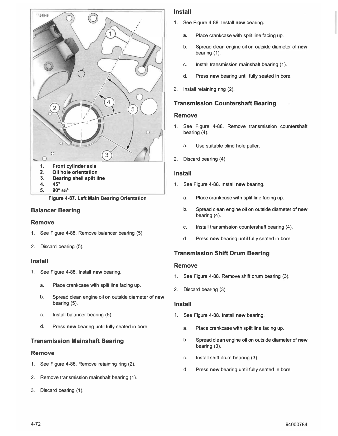
1. Transmission mainshaft bearing
Install 2. Screw (2)
1. See Figure 4-86. Install new bearing. 3. Retainer plate
4. Transmission countershaft bearing
5. Shift drum bearing
a. Place crankcase with split line facing up.
6. Retaining ring
b. Spread clean engine oil on outside diameter of new 7. Balancer bearing
bearing (4). Figure 4-86. Right Crankcase Bearing Replacement
REPAIR LEFT CRANKCASE HALF
c. Install transmission countershaft bearing (4).
d. Press new bearing until fully seated in bore. PART NUMBER TOOL NAME
HD-52961 MAIN BEARING INSTALLATION TOOL
2. Install retaining plate (3).
Main Bearing
3. Install screws (2). Tighten.
Remove
Torque: 80-97 in-lbs (9-11 N·m) Screw, retainging plate,
transmission mainshaft bearing 1. See Figure 4-87. Remove main bearing using special tool.
Special Tool: MAIN BEARING INSTALLATION TOOL
Transmission Shift Drum Bearing (HD-52961)
Remove 2. Discard bearing halves.
1. See Figure 4-86. Remove retaining ring (6).
Install
2. Remove shift drum bearing (5).
1. See Figure 4-87. Install new bearing halves. Use special
tool.
3. Discard bearing (5).
Special Tool: MAIN BEARING INSTALLATION TOOL
(HD-52961)
Install
a. O rient bearing half oil holes (2).
1. See Figure 4-86. Install new bearing.
b. O rient bearing half split lines (3).
a. Place crankcase with split line facing up.
b. Spread clean engine oil on outside diameter of new
bearing (5).
c. Install shift drum bearing (5).
94000784 4-71
Install
© 1. See Figure 4-88. Install new bearing.
1 / a. Place crankcase with split line facing up.
I
b. Spread clean engine oil on outside diameter of new
bearing (1).
1---
I
1
c. Install transmission mainshaft bearing (1).
d. Press new bearing until fully seated in bore.
t
2. Install retaining ring (2).
0
i__ ,
I ;
__.>--'"
- - - --- - !� - - -) 4
I -
\
00 Transmission Countershaft Bearing
Remove
1. See Figure 4-88. Remove transmission countershaft
bearing (4).
a. Use suitable blind hole puller.
0 3
2. Discard bearing (4).
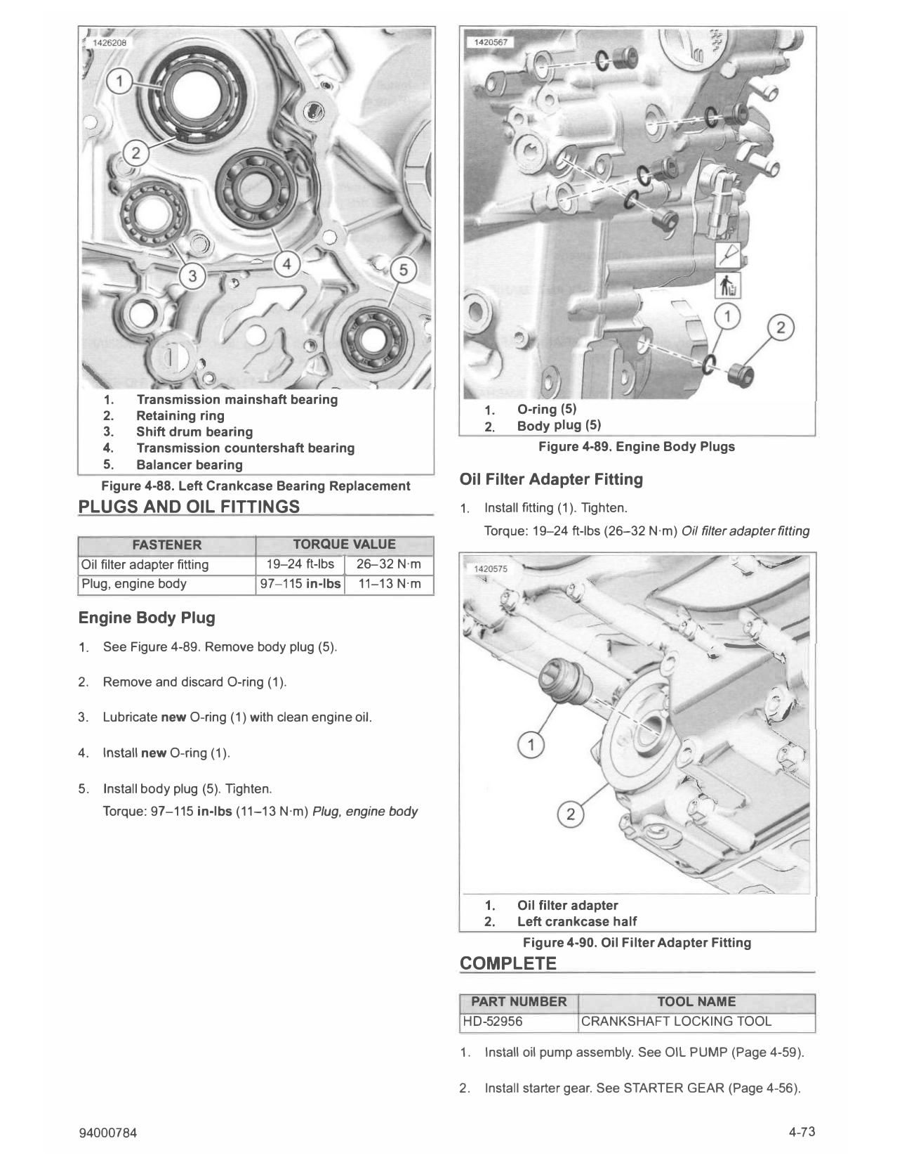
1. Front cylinder axis
2. Oil hole orientation Install
3. Bearing shell split line
4. 45° 1. See Figure 4-88. Install new bearing.
5. 90° ±5°
Figure 4-87. Left Main Bearing Orientation a. Place crankcase with split line facing up.
Balancer Bearing b. Spread clean engine oil on outside diameter of new
bearing (4).
Remove
c. Install transmission countershaft bearing (4).
1. See Figure 4-88. Remove balancer bearing (5).
d. Press new bearing until fully seated in bore.
2. Discard bearing (5).
Transmission Shift Drum Bearing
Install
Remove
1. See Figure 4-88. Install new bearing.
1. See Figure 4-88. Remove shift drum bearing (3).
a. Place crankcase with split line facing up.
2. Discard bearing (3).
b. Spread clean engine oil on outside diameter of new
bearing (5). Install
c. Install balancer bearing (5). 1. See Figure 4-88. Install new bearing.
d. Press new bearing until fully seated in bore. a. Place crankcase with split line facing up.
Transmission Mainshaft Bearing b. Spread clean engine oil on outside diameter of new
bearing (3).
Remove
c. Install shift drum bearing (3).
1. See Figure 4-88. Remove retaining ring (2).
d. Press new bearing until fully seated in bore.
2. Remove transmission mainshaft bearing (1).
3. Discard bearing (1).
4-72 94000784
1. Transmission mainshaft bearing
2. Retaining ring 1. O-ring (5)
3. Shift drum bearing 2. Body plug (5)
4. Transmission countershaft bearing Figure 4-89. Engine Body Plugs
5. Balancer bearing
Figure 4-88. Left Crankcase Bearing Replacement Oil Filter Adapter Fitting
PLUGS AND OIL FITTINGS 1. Install fitting (1). Tighten.
Torque: 19-24 ft-lbs (26-32 N·m) Oil filter adapter fitting
FASTENER TORQUE VALUE
Oil filter adapter fitting 19-24 ft-lbs I 26-32 N·m
Plug, engine body 97-115 in-lbs I 11-13 N·m
Engine Body Plug
:,
1. See Figure 4-89. Remove body plug (5). , �
-
/�
2. Remove and discard O-ring (1). � \.
(- f.,
3. Lubricate new O-ring (1) with clean engine oil. ,�'
4. Install new O-ring (1).
5. Install body plug (5). Tighten.
Torque: 97-115 in-lbs (11-13 N·m) Plug, engine body
1. Oil filter adapter
2. Left crankcase half
Figure 4-90. Oil Filter Adapter Fitting
COMPLETE
PART NUMBER TOOL NAME
HD-52956 CRANKSHAFT LOCKING TOOL
1. Install oil pump assembly. See OIL PUMP (Page 4- 59).
2. Install starter gear. See STARTER GEAR (Page 4-56).
94000784 4-73
3. Install oil pump drive. See OIL PUMP DRIVE (Page 4-57). 12. Install phaser solenoids with plate assembly. See PHASER
SOLENOIDS (Page 4-22).
a. Install chain guides.
13. Install camshaft covers. See CAMSHAFT COVERS
b. Install balancer gear. (Page 4-21).
4. Install alternator. See ALTERNATOR (Page 8-8). 14. Install cylinder head covers. See CYLINDER HEAD
COVERS (Page 4-19).
5. Install cylinders. See CYLINDERS (Page 4-43).
15. Remove camshaft timing sensor. See CAMSHAFT TIMING
6. Install cylinder heads. See CYLINDER HEADS SENSORS (Page 8-48).
(Page 4-34).
16. Remove coil pack. See IGNITION COIL (Page 8-16).
a. Install camshaft drive chain covers.
17. Install oil cooler hoses. See OIL COOLER (Page 4-17).
7. Install coolant manifold. See COOLANT MANIFOLD
(Page 4-51). 18. Install starter. See STARTER (Page 8-5).
8. Install clutch primary drive gear. See CRANKSHAFT AND 19. Remove crankshaft locking tool. See CRANKSHAFT
CONNECTING RODS (Page 4-77). LOCKOUT (Page 4-18).
Special Tool: CRANKSHAFT LOCKING TOOL (HD-52956)
9. Install sprockets and timing chain. See CAMSHAFT
SPROCKET AND TIMING CHAIN (Page 4-24). 20. Install engine. See REPLACE ENGINE (Page 4-60).
10. Install clutch. See CLUTCH (Page 5-12). 21. Install output sprocket. See OUTPUT SPROCKET
(Page 5-6).
11. Install camshafts. See CAMSHAFTS AND PHASERS
(Page 4-38). 22. Install main fuse. See POWER DISCONNECT
(Page 8-4).
4-74 94000784