4.29 Crankshaft And Connecting Rods
Fragment manuala — str. 281–283
📋 Tekst do skopiowania (OCR/wyszukiwanie)
CRANKSHAFT AND CONNECTING RODS 4.29
P REPARE b. Install screws (1). Tighten in criss-cross pattern.
Torque: 24-27 ft-lbs (32-36 N·m) Crankshaft primary
1. Remove main fuse. See POWER DISCON NECT gear screws
(Page 8-4).
2. Remove engine. See REPLACE ENGINE (Page 4-60).
3. Remove camshaft drive sprocket. See CAMSHAFT
SPROCKET AN D TIMING CHAIN (Page 4-24).
4. Separate crankcase. See CRANK CASE (Page 4-66).
REMOVE
PART NUMBER TOOL NAME
HD-52957 CRANKSHAFT PROTECTOR
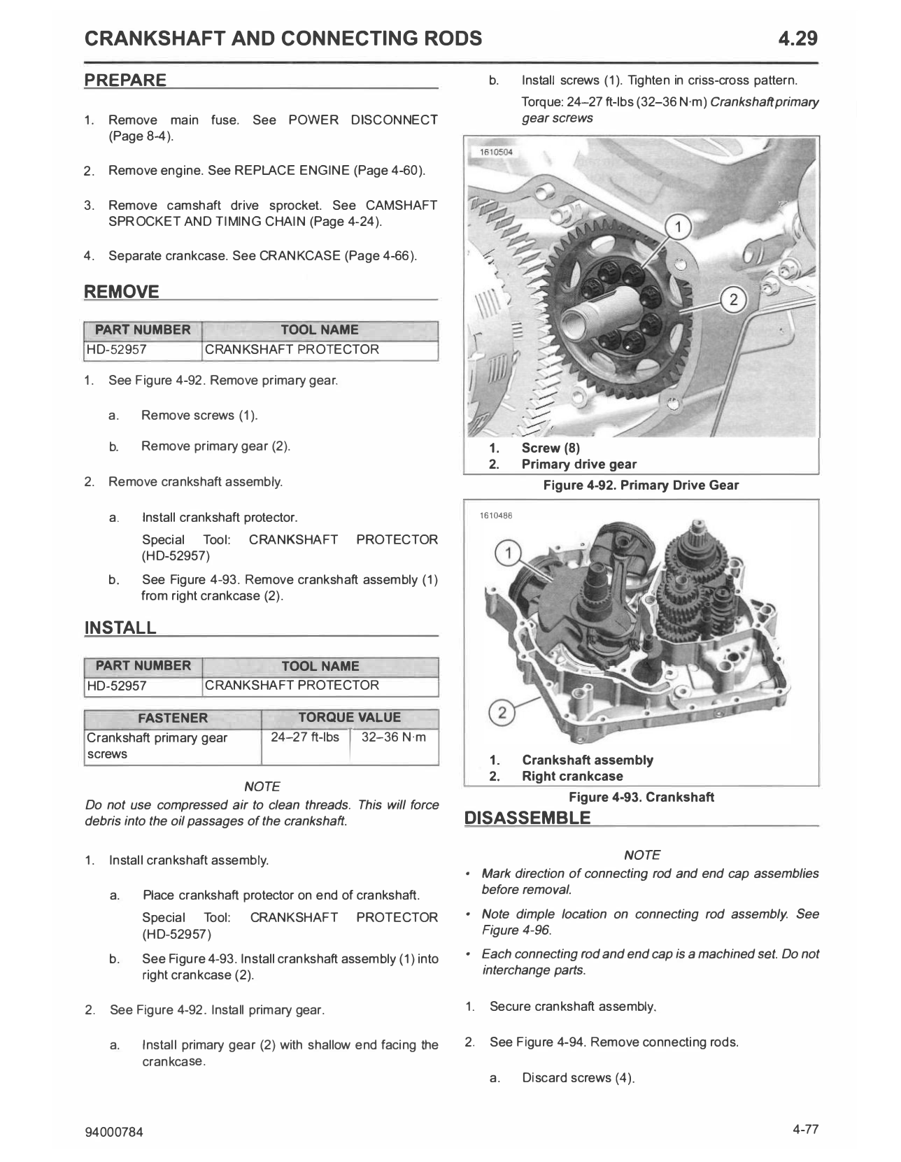
1. See Figure 4-92. Remove primary gear.
a. Remove screws (1).
b. Remove primary gear (2). 1. Screw (8)
2. Primary drive gear
2. Remove crankshaft assembly. Figure 4-92. Primary Drive Gear
a. Install crankshaft protector. 1610488
Special Tool: CRANKSHAFT PROTECTOR
(HD-52957)
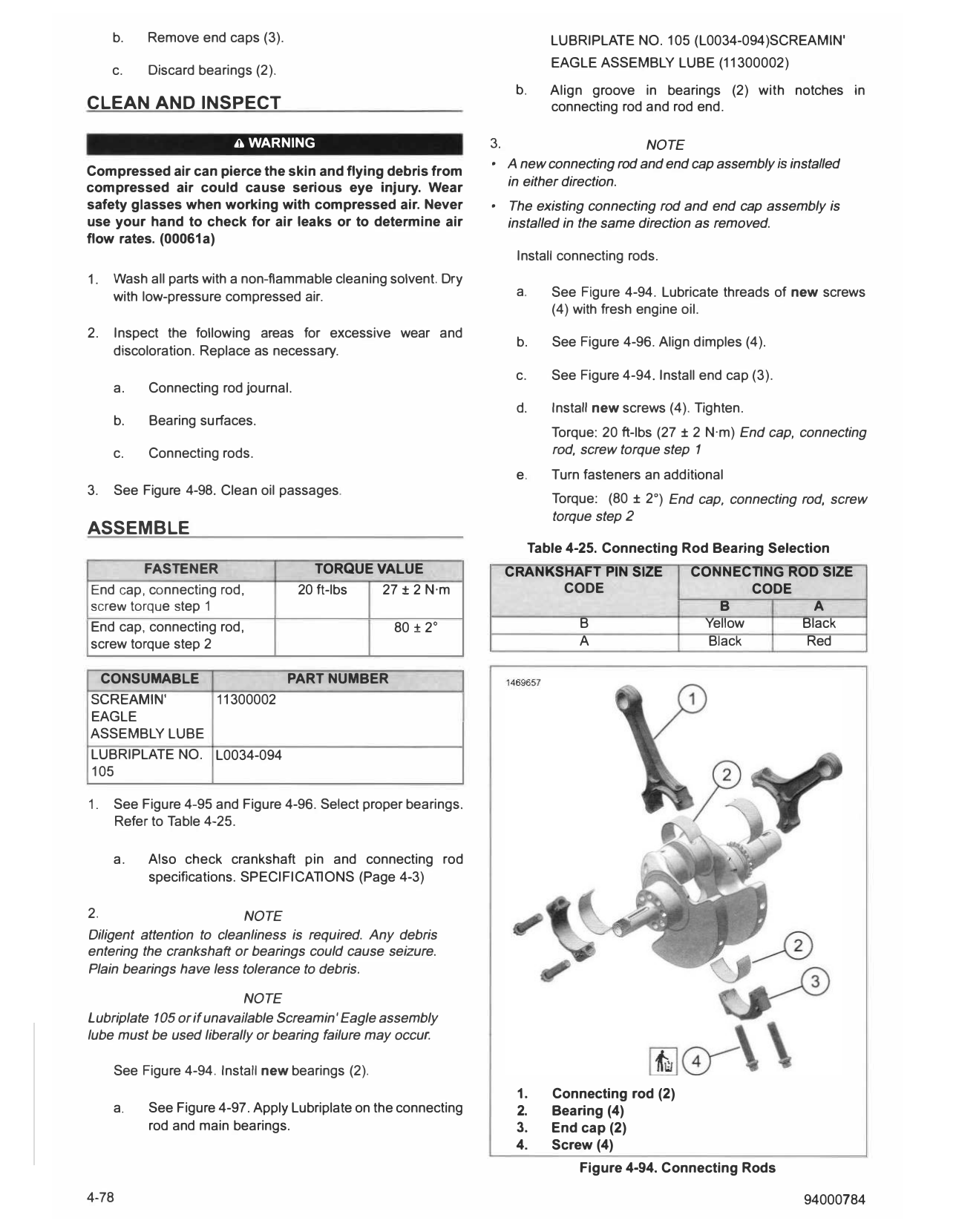
b. See Figure 4-93. Remove crankshaft assembly (1)
from right crankcase (2).
INSTALL
PART NUMBER TOOL NAME
HD-52957 CRANKSHAFT PROTECTOR
FASTENER TORQUE VALUE
Crankshaft primary gear 24-27 ft-lbs 32-36 N·m
I
screws 1. Crankshaft assembly
2. Right crankcase
NOTE
Figure 4-93. Crankshaft
Do not use compressed air to clean threads. This will force
debris into the oil passages of the crankshaft. DISASSEMBLE
1. Install crankshaft assembly. NOTE
• Mark direction of connecting rod and end cap assemblies
a. Place crankshaft protector on end of crankshaft. before removal.
Special Tool: CRANKSHAFT PROTECTOR • Note dimple location on connecting rod assembly. See
(HD-52957) Figure 4-96.
b. See Figure 4-93. Install crankshaft assembly (1) into • Each connecting rod and end cap is a machined set. Do not
right crankcase (2). interchange parts.
2. See Figure 4-92. Install primary gear. 1. Secure crankshaft assembly.
a. Install primary gear (2) with shallow end facing the 2. See Figure 4-94. Remove connecting rods.
crankcase.
a. Discard screws (4).
94000784 4-77
b. Remove end caps (3). LUBRIPLATE NO. 105 (L0034-094)SCREAMIN'
EAGLE ASSEMBLY LUBE (11300002)
c. Discard bearings (2).
b. Align groove in bearings (2) with notches in
CLEAN AND INSPECT connecting rod and rod end.
A WARNING 3. NOTE
• A new connecting rod and end cap assembly is installed
Compressed air can pierce the skin and flying debris from
compressed air could cause serious eye injury. Wear in either direction.
safety glasses when working with compressed air. Never • The existing connecting rod and end cap assembly is
use your hand to check for air leaks or to determine air installed in the same direction as removed.
flow rates. (00061a)
Install connecting rods.
1. Wash all parts with a non-flammable cleaning solvent. Dry
with low-pressure compressed air. a. See Figure 4-94. Lubricate threads of new screws
(4) with fresh engine oil.
2. Inspect the following areas for excessive wear and
b. See Figure 4-96. Align dimples (4).
discoloration. Replace as necessary.
c. See Figure 4-94. Install end cap (3).
a. Connecting rod journal.
d. Install new screws (4). Tighten.
b. Bearing surfaces.
Torque: 20 ft-lbs (27 ± 2 N·m) End cap, connecting
c. Connecting rods. rod, screw torque step 1
e. T urn fasteners an additional
3. See Figure 4-98. Clean oil passages.
Torque: (80 ± 2°) End cap, connecting rod, screw
torque step 2
ASSEMBLE
Table 4-25. Connecting Rod Bearing Selection
FASTENER TORQUE VALUE CRANKSHAFT PIN SIZE CONNECTING ROD SIZE
End cap, connecting rod, 20 ft-lbs 27 ± 2 N·m CODE CODE
screw torque step 1 B A
End cap, connecting rod, 80 ± 2° B Yellow Black
screw torque step 2 A Black Red
CONSUMABLE PART NUMBER
SCREAM IN' 11300002
EAGLE
ASSEMBLY LUBE
LUBRIPLAT E NO. L0034-094
105
1. See Figure 4-95 and Figure 4-96. Select proper bearings.
Refer to Table 4-25.
a. Also check crankshaft pin and connecting rod
specifications. SPECIFICATIONS (Page 4-3)
2. NOTE
Diligent attention to cleanliness is required. Any debris
entering the crankshaft or bearings could cause seizure.
Plain bearings have less tolerance to debris.
NOTE
Lubriplate 105 or if unavailable Screamin' Eagle assembly
lube must be used liberally or bearing failure may occur.
See Figure 4-94. Install new bearings (2).
1. Connecting rod (2)
a. See Figure 4-97. Apply Lubriplate on the connecting 2. Bearing (4)
rod and main bearings. 3. End cap (2)
4. Screw (4)
Figure 4-94. Connecting Rods
4-78 94000784
1469854
0f:=_r::>@
24100189
012AA
0@ 0
0
5 s @�
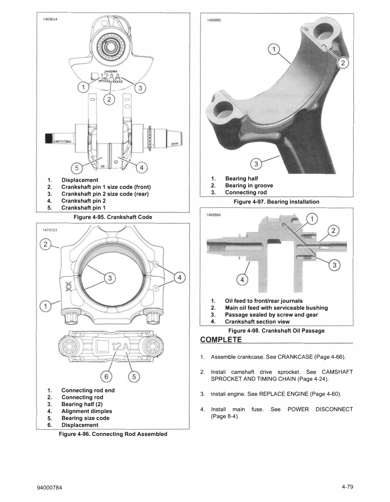
1. Displacement 1. Bearing half
2. Crankshaft pin 1 size code (front) 2. Bearing in groove
3. Crankshaft pin 2 size code (rear) 3. Connecting rod
4. Crankshaft pin 2 Figure 4-97. Bearing Installation
5. Crankshaft pin 1
Figure 4-95. Crankshaft Code
1470133
0-
1. Oil feed to front/rear journals
2. Main oil feed with serviceable bushing
3. Passage sealed by screw and gear
4. Crankshaft section view
Figure 4-98. Crankshaft Oil Passage
COMPLETE
1. Assemble crankcase. See CRANKCASE (Page 4-66).
2. Install camshaft drive sprocket. See CAMSHAFT
SPROCKET AND TIMING CHAIN (Page 4-24).
1. Connecting rod end
3. Install engine. See REPLACE ENGINE (Page 4-60).
2. Connecting rod
3. Bearing half (2)
4. Alignment dimples 4. Install main fuse. See POWER DISCONNECT
5. Bearing size code (Page 8-4).
6. Displacement
Figure 4-96. Connecting Rod Assembled
94000784 4-79