4.26 Replace Engine
Fragment manuala — str. 264–269
📋 Tekst do skopiowania (OCR/wyszukiwanie)
REPLACE ENGINE 4.26
REMOVE 16. Disconnect electrical connectors.
PART NUMBER TOOLNAME a. ECM
HD-52960 ENGINE SUPPORT PLATE
b. Top coils.
HD-53022 POWERTRAIN R&R FIXTURE
C. Sensor jumper.
1. Remove fairing. See FAIRING (Page 3-89).
d. Phaser solenoids.
2. Remove seat. See SEAT (Page 3-113).
e. Cam timing sensors.
3. NOTE
f. Knock sensor.
When mounting hardware is removed, fuel tank may move.
Protect fuel tank from damage on engine guard equipped
g. Coolant temperature sensor.
vehicles.
h. Oil pressure switch.
Purge fuel line. See PURGE FUEL LINE (Page 6-9).
i. Rear active suspension.
4. Remove fuel tank. See FUEL TANK (Page 6-13).
17. Remove ECM. See ELECTRONIC CONTROL MODULE
5. Remove steering head covers. See SIDE COVERS (ECM) (Page 8-38).
(Page 3-52).
18. Remove cylinder head cover caddy. See CYLINDER HEAD
a. Remove right side steering head cover. COVER CADDY (Page 8-60).
b. Remove left side steering head cover. 19. Cut right side wire harness guide cable straps.
6. Remove main fuse. See POWER DISCONNECT 20. Disconnect connectors at front electrical caddy. See
(Page 8-4). FRONT ELECTRICAL CADDY (Page 8-58).
7. Remove tail section cross-member. See FRAME a. Disconnect right turn signal.
CROSSMEMBER (Page 3-123).
b. Disconnect air temp sensor.
8. Detach brake line clamps. See Brake Line: Front Caliper
to ABS Module in BRAKE LINES (Page 3-40). 21. Remove skid plate. See SKID PLATE (Page 3-92).
a. Detach brake line clamp from cylinder head cover 22. If equipped: Remove engine guards. See RADIATOR
caddy. (Page 7-18).
b. Detach rear brake line clamp.
23. Remove fairing lowers. See RADIATOR (Page 7-18).
9. Remove air box assembly. See AIR BOX (Page 6-3).
24. Drain engine coolant. See COOLANT (Page 7-8).
10. Remove spark plug cables. See SPARK PLUG CABLES
25. Drain engine oil and discard oil filter. See REPLACE
(Page 8-15).
ENGINE Oil AND FILTER (Page 2-7).
11. Remove side-mount ignition coil. See IGNITION COIL
26. If equipped: Disconnect purge valve from voltage regulator
(Page 8-16).
mounting bracket. See PURGE SOLENOID:
EVAPORATIVE EMISSIONS (Page 6-40).
12. If equipped: Disconnect EVAP line at front of coil mount.
27. Disconnect both battery cables. See INSPECT BATTERY
13. Remove coil mount. See IGNITION COIL (Page 8-16). (Page 2-38).
14. Disconnect Sensor harness from engine wire harness. 28. Disconnect solenoid to starter cable. See STARTER
See . SOLENOID (Page 8-7).
15. Remove induction module. See INDUCTION MODULE 29. Remove voltage regulator mount. See VOLTAGE
(Page 6-28). REGULATOR (Page 8-13).
a. Remove voltage regulator.
4-60 94000784
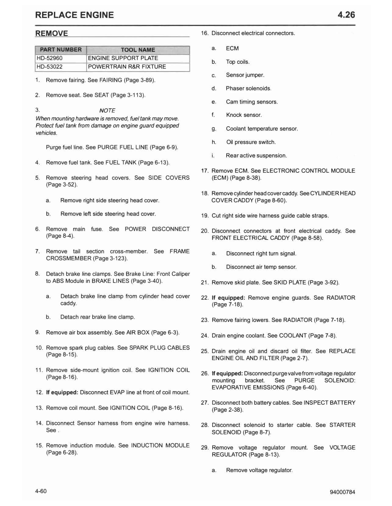
b. Remove voltage regulator mounting bracket. See Figure 4-69. Install support plate to bottom of engine.
30. Remove battery. See INSPECT BATTERY (Page 2-38).
31. Remove coolant overflow tank. See COOLANT
OVERFLOW TANK (Page 7-14).
32. Remove radiator. See RADIATOR (Page 7-18).
33. If equipped: Remove charcoal canister. See CHARCOAL
CANISTER: EVAPORATIVE EMISSIONS (Page 6-41).
Figure 4-69. Engine Support Plate
34. Remove battery tray. See BATTERY TRAY (Page 8-63). Special Tool: ENGINE SUPPORT PLATE (HD-52960)
35. Disconnect electrical connectors and ground connections. 47. Detach rear brake caliper. Secure out of the way. See
REAR BRAKE CALIPER (Page 3-38).
a. Ground cable (dirty ground).
a. Remove P-clamps from rear fork.
b. Main harness ground (dirty ground).
48. Remove rear wheel. See REAR WHEEL (Page 3-11).
c. Crank position sensor.
49. Secure ABS sensor out of the way.
36. Disconnect 02 sensor caddy. See xxxx.
50. Remove drive chain. See DRIVE CHAIN (Page 5-5).
a. Disconnect 02 sensors.
51. Disconnect rear shock. See REAR SHOCK ABSORBER
b. Secure out of way.
(Page 3-78).
37. Remove jiffy stand. See JIFFY STAND (Page 3-109).
a. Disconnect top of rear shock from cylinder head.
38. If equipped: Remove center stand. See CENTER STAND b. Disconnect suspension links from suspension
(Page 3-111 ). mounting bracket.
39. Remove left foot control bracket. See RIDER FOOTRESTS 52. Loosen midframe fasteners. See FRAME (Page 3-118).
(Page 3-104).
53. Remove rear fork with shock assembly. See REAR FORK
40. Remove front chain guard. See CHAIN GUARDS (Page 3-74).
(Page 3-76).
NOTE
41. NOTE Retain midframe for the following steps.
Use rear brake to stop rotation of rear wheel when
removing transmission sprocket nut. 54. Reinstall left midframe-to-head top screw. Tighten finger
tight.
Loosen transmission sprocket nut. See OUTPUT
SPROCKET (Page 5-6). 55. Detach clutch cable from engine and actuator. See
CLUTCH CONTROL (Page 3-82).
42. Detach right foot control bracket. Secure out of the way.
See RIDER FOOTRESTS (Page 3-104). a. Relocate clutch cable to front frame and secure.
43. Remove exhaust system. See EXHAUST SYSTEM 56. Install powertrain R&R fixture.
(Page 6-37).
Special Tool: POWERTRAIN R&R FIXTURE (HD-53022)
a. Leave rear port extension header on engine. a. Remove both rear head-to-front frame bolts from the
left side. See Front Frame in FRAME (Page 3-118).
44. Remove top chain guard. See CHAIN GUARDS
(Page 3-76).
45. Disconnect gear position sensor. See GEAR POSITION
SENSOR (Page 8-50).
46. NOTE
Using a flatjack, without the rubber pad on the top surface,
will help when removing the powertrain.
94000784 4-61
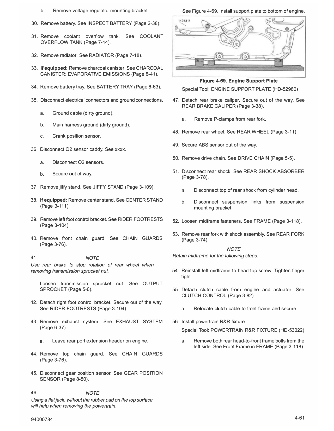
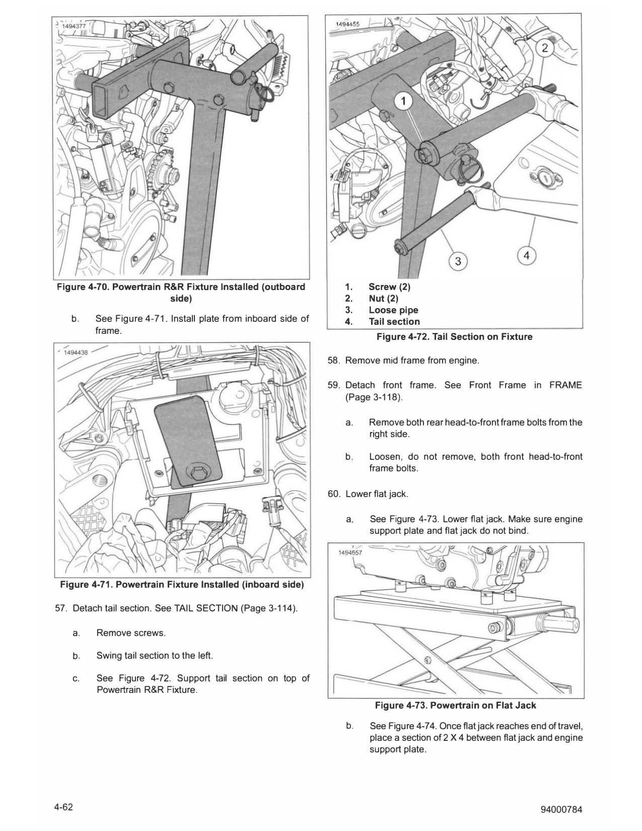
Figure 4-70. Powertrain R&R Fixture Installed (outboard 1. Screw (2)
side) 2. Nut (2)
3. Loose pipe
b. See Figure 4-71. Install plate from inboard side of 4. Tail section
frame.
Figure 4-72. Tail Section on Fixture
58. Remove mid frame from engine.
59. Detach front frame. See Front Frame in FRAME
(Page 3-118).
a. Remove both rear head-to-front frame bolts from the
right side.
b. Loosen, do not remove, both front head-to-front
frame bolts.
60. Lower flat jack.
a. See Figure 4-73. Lower flat jack. Make sure engine
support plate and flat jack do not bind.
Figure 4-71. Powertrain Fixture Installed (inboard side)
57. Detach tail section. See TAIL SECTION (Page 3-114).
a. Remove screws.
b. Swing tail section to the left.
c. See Figure 4-72. Support tail section on top of
Powertrain R&R Fixture.
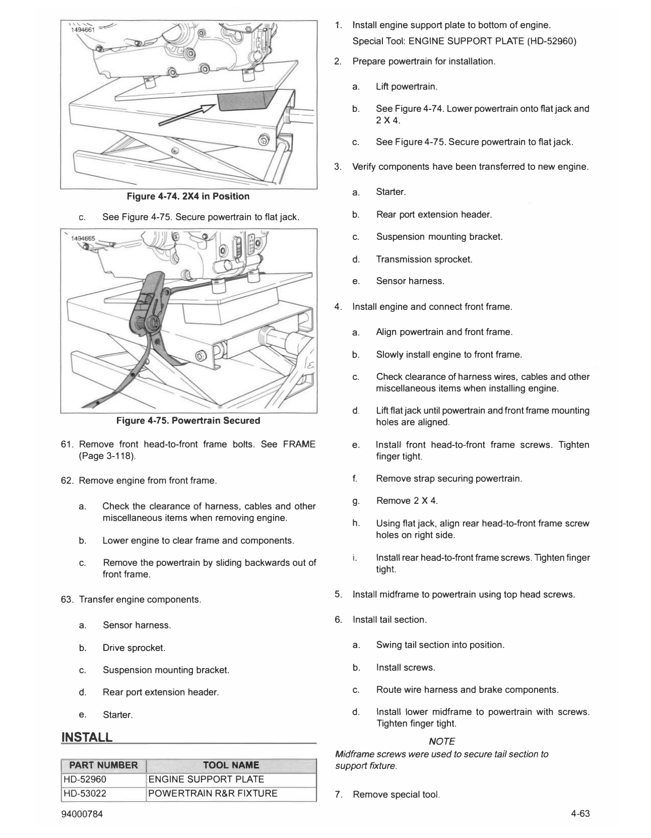
Figure 4-73. Powertrain on Flat Jack
b. See Figure 4-74. Once flat jack reaches end of travel,
place a section of 2 X 4 between flat jack and engine
support plate.
4-62 94000784
1. Install engine support plate to bottom of engine.
Special Tool: ENGINE SUPPORT PLATE (HD-52960)
2. Prepare powertrain for installation.
a. Lift powertrain.
b. See Figure 4-74. Lower powertrain onto flat jack and
2X4.
c. See Figure 4-75. Secure powertrain to flat jack.
3. Verify components have been transferred to new engine.
Figure 4-74. 2X4 in Position a. Starter.
C. See Figure 4-75. Secure powertrain to flat jack. b. Rear port extension header.
c. Suspension mounting bracket.
d. Transmission sprocket.
e. Sensor harness.
4. Install engine and connect front frame.
a. Align powertrain and front frame.
b. Slowly install engine to front frame.
c. Check clearance of harness wires, cables and other
miscellaneous items when installing engine.
d. Lift flat jack until powertrain and front frame mounting
Figure 4-75. Powertrain Secured holes are aligned.
61. Remove front head-to-front frame bolts. See FRAME e. Install front head-to-front frame screws. Tighten
(Page 3-118). finger tight.
62. Remove engine from front frame. f. Remove strap securing powertrain.
g. Remove 2 X 4.
a. Check the clearance of harness, cables and other
miscellaneous items when removing engine.
h. Using flat jack, align rear head-to-front frame screw
holes on right side.
b. Lower engine to clear frame and components.
i. Install rear head-to-front frame screws. Tighten finger
c. Remove the powertrain by sliding backwards out of
tight.
front frame.
5. Install midframe to powertrain using top head screws.
63. Transfer engine components.
6. Install tail section.
a. Sensor harness.
b. Drive sprocket. a. Swing tail section into position.
c. Suspension mounting bracket. b. Install screws.
d. Rear port extension header. c. Route wire harness and brake components.
e. Starter. d. Install lower midframe to powertrain with screws.
Tighten finger tight.
INSTALL NOTE
Midframe screws were used to secure tail section to
PART NUMBER TOOL NAME support fixture.
HD-52960 ENGINE SUPPORT PLATE
HD-53022 POWERTRAIN R&R FIXTURE 7. Remove special tool.
94000784 4-63
Special Tool: POWERTRAIN R&R FIXTURE (HD-53022) 20. Attach right foot control bracket. See RIDER FOOTRESTS
(Page 3-104).
8. Install rear head-to-front frame screws on left side. Tighten
finger tight.
21. Torque front drive sprocket nut while applying rear brake.
See OUTPUT SPROCKET (Page 5-6).
9. Tighten all front frame screws in sequence. See FRAME
(Page 3-118).
22. Install front chain guard. See CHAIN GUARDS
(Page 3-76).
10. Install clutch cable. See CLUTCH CONTROL (Page 3-82).
23. Install left foot control bracket. See RIDER FOOTRESTS
11. Route and connect electrical connectors. (Page 3-104).
a. Gear position sensor 24. If equipped: Install center stand. See CENTER STAND
(Page 3-111).
12. Install rear fork with shock assembly. See REAR FORK
(Page 3-74). 25. Install jiffy stand. See JIFFY STAND (Page 3-109).
a. Install rear fork pivot shaft. 26. Install starter caddy.
b. Connect top of rear shock to cylinder head.
27. Route and connect electrical connectors and connections.
C. Install suspension links.
a. 02 sensors
13. Tighten screws in the following sequence.
b. Ground cable (dirty ground)
a. Top shock screw. See REAR SHOCK ABSORBER c. Main harness ground (dirty ground)
(Page 3-78).
d. Crank position sensor.
b. Bottom shock screw to spider bracket.
28. Install battery tray. See BATTERY TRAY (Page 8-63).
c. Midframe screws.
d. Swing arm pivot shaft. 29. Install overflow tank. See COOLANT OVERFLOW TANK
(Page 7-14).
e. Pivot shaft pinch screw.
30. If equipped: Install charcoal canister. See CHARCOAL
f. Top tail section screws. CANISTER: EVAPORATIVE EMISSIONS (Page 6-41).
14. Install rear wheel. See REAR WHEEL (Page 3-11). 31. Install battery. See INSPECT BATTERY (Page 2-38).
15. Install drive chain. See DRIVE CHAIN (Page 5-5). 32. Install voltage regulator. See VOLTAGE REGULATOR
(Page 8-13).
16. Attach rear brake caliper. See REAR BRAKE CALIPER
(Page 3-38). 33. If equipped: Connect carbon canister purge valve to
voltage regulator mounting bracket. See PURGE
a. Route brake line along rear fork. Refer to BRAKE SOLENOID: EVAPORATIVE EMISSIONS (Page 6-40).
LINES (Page 3-40).
34. Install radiator. See RADIATOR (Page 7-18).
b. Secure brake line and rear wheel speed sensor
harness with P-clamps. 35. Install cylinder head cover caddy. [NEED LOCATION FOR
LINK]
c. Install rear wheel speed sensor wire retainers to rear
brake line. See tape for location reference.
36. Install ECM. See ELECTRONIC CONTROL MODULE
(ECM) (Page 8-38).
17. Install top chain guard. See CHAIN GUARDS (Page 3-76).
37. Route and connect electrical connectors and connections.
18. Remove engine support plate.
Special Tool: ENGINE SUPPORT PLATE (HD-52960) a. ECM
NOTE
Rear port extension header should be installed on engine. b. Top coils
c. Sensor jumper.
19. Install exhaust system. See EXHAUST SYSTEM
(Page 6-37). d. Phaser solenoids
4-64 94000784
e. Cam timing sensor 47. Install spark plug cables. See SPARK PLUG CABLES
(Page 8-15).
f. Knock sensor
48. Finish coolant bleed procedure. See COOLANT
g. Coolant temperature sensor (Page 7-8).
h. Oil pressure switch
49. Check engine oil level. See REPLACE ENGINE OIL AND
i. Rear active suspension FILTER (Page 2-7).
38. Install tail section crossmember. See FRAME (Page 3-118). 50. Install engine guards. See RADIATOR (Page 7-18).
a. Make sure that the double clamp and brakeline is a. Install fairing lowers.
installed on the top of the inner left mid-frame.
b. If equipped: Install engine guards.
39. Install induction module. See INDUCTION MODULE
(Page 6-28). 51. Install steering head covers. See SIDE COVERS
(Page 3-52).
40. Install airbox assembly. See AIR BOX (Page 6-3).
a. Install right side steering head cover.
41. Install fuel tank. See FUEL TANK (Page 6-13). b. Install left side steering head cover.
42. Install seat. See SEAT (Page 3-113). 52. Install fairing. See FAIRING (Page 3-89).
43. Install main fuse. See POWER DISCONNECT 53. Run motorcycle until engine is at normal operating
(Page 8-4). temperature.
44. Install new filter and add new engine oil. See REPLACE a. Check clutch operation. Adjust if needed.
ENGINE OIL AND FILTER (Page 2-7).
b. Check instrument lamps.
45. Start bleed procedure, add coolant, and burp cylinder
heads. See COOLANT (Page 7-8). c. Check for leaks.
46. Install side-mount ignition coil. See IGNITION COIL d. Check engine oil level (hot) resting on jiffy stand.
(Page 8-16).
54. Install skid plate. See SKID PLATE (Page 3-92).
94000784 4-65