4.25 Oil Pump
Fragment manuala — str. 263
📋 Tekst do skopiowania (OCR/wyszukiwanie)
OIL PUMP 4.25
PREPARE 2. Install oil pump assembly.
1. Remove main fuse. See POWER DISCONNECT a. Clean grove in oil pump (5) from all residual oil and
(Page 8-4). debris.
2. Install crankshaft lockout tool. See CRANKSHAFT b. Install new gasket (4).
LOCKOUT (Page 4-18).
c. Install oil pump (5).
3. Remove coolant manifold. See COOLANT MANIFOLD d. Install screws (6). Tighten center screw first followed
(Page 4-51). by criss-cross pattern.
Torque: 80-97 in-lbs (9-11 N·m) Oil pump (pressure
4. Remove alternator. See ALTERNATOR (Page 8-8).
side) screws
5. Remove oil pump drive. See OIL PUMP DRIVE
(Page 4-57).
REMOVE
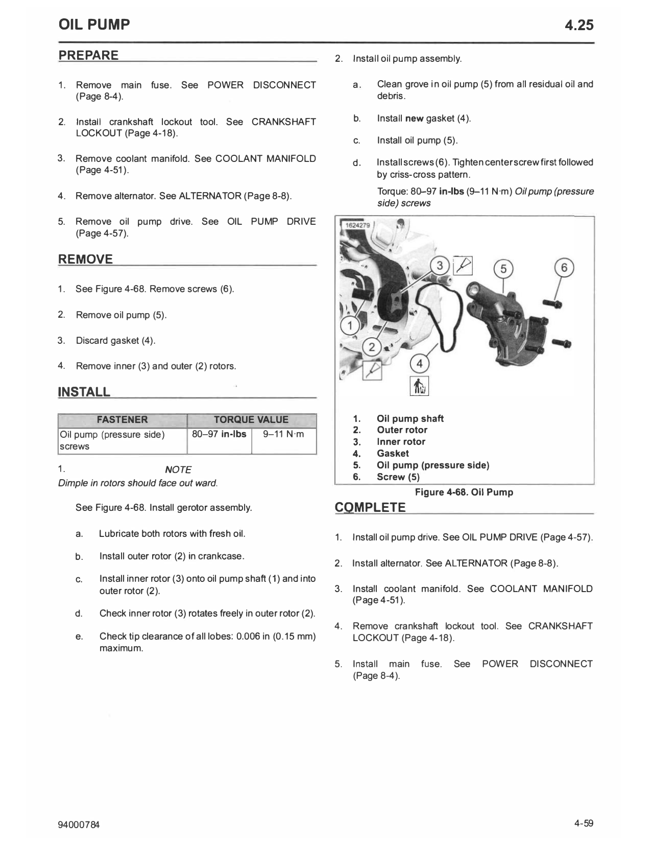
1. See Figure 4-68. Remove screws (6).
2. Remove oil pump (5).
3. Discard gasket (4).
4. Remove inner (3) and outer (2) rotors.
INSTALL
FASTENER TORQUE VALUE 1. Oil pump shaft
Oil pump (pressure side) 80-97 in-lbs 9-11 N·m 2. Outer rotor
I
screws 3. Inner rotor
4. Gasket
1. NOTE 5. Oil pump (pressure side)
6. Screw (5)
Dimple in rotors should face out ward.
Figure 4-68. Oil Pump
See Figure 4-68. Install gerotor assembly. COMPLETE
a. Lubricate both rotors with fresh oil. 1. Install oil pump drive. See OIL PUMP DRIVE (Page 4-57).
b. Install outer rotor (2) in crankcase.
2. Install alternator. See ALTERNATOR (Page 8-8).
c. Install inner rotor (3) onto oil pump shaft (1) and into
outer rotor (2). 3. Install coolant manifold. See COOLANT MANIFOLD
(Page 4-51).
d. Check inner rotor (3) rotates freely in outer rotor (2).
4. Remove crankshaft lockout tool. See CRANKSHAFT
e. Check tip clearance of all lobes: 0.006 in (0.15 mm) LOCKOUT (Page 4-18).
maximum.
5. Install main fuse. See POWER DISCONNECT
(Page 8-4).
94000784 4-59