4.22 Coolant Manifold
Fragment manuala — str. 255–259
📋 Tekst do skopiowania (OCR/wyszukiwanie)
COOLANT MANIFOLD 4.22
PREPARE Coolant Tubes
1. See Figure 4-55. Remove coolant tubes (5).
1. Remove main fuse. See POWER DISCONNECT
(Page 8-4).
2. Discard O-rings (4).
2. Remove front skid plate. See SKID PLATE (Page 3-92).
Coolant Pump
3. Drain engine oil. See REPLACE ENGINE OIL AND FILTER
1. See Figure 4-57. Remove coolant pump screws.
(Page 2-7).
2. Remove coolant pump.
4. Disconnect alternator harness from voltage regulator. See
ALTERNATOR (Page 8-8). NOTE
Place a shop towel on the coolant manifold to protect the
5. Remove radiator. See RA DIATOR (Page 7-18). manifolds sealing surface.
6. Disconnect oil cooler hoses. See OIL COOLER a. See Figure 4-58. Using a small screw drive, gently
(Page 4-17). pry upward between the coolant pump (1) and
coolant manifold (2).
7. Disconnect coolant temperature sensor connector. See
ENGINE COOLANT TEMPERATURE (ECT) SENSOR b. See Figure 4-59. Lift straight upward, remove coolant
(Page 7-17). pump.
8. Disconnect crankshaft position sensor connector. See 3. See Figure 4-60. Remove O-rings.
CRA NKSHAFT POSITION SENSOR (CKP) (Page 8-46).
a. Discard the small (1) and large (2) O-rings if coolant
9. Remove shift lever. See RIDER FOOTRESTS (Page 3-104). pump is being reused.
10. Remove Thermostat housing. See THERMOSTAT Stator
HOUSING (Page 7-11).
1. See Figure 4-61. Disconnect and remove terminals (2)
REMOVE from stator connector (1).
2. See Figure 4-62. Remove stator screws (1).
PART NUMBER TOOL NAME
HD-45340 GASKET A LIGNMENT DOWELS NOTE
T he stators harness grommet has a chance of leaking if
Coolant Manifold used more than one time.
1. See Figure 4-55. Remove screws (6 and 7).
3. See Figure 4-63. Remove stator and harness, discard.
2. See Figure 4-56. Install gasket alignment dowels (A) into
position marked. INSTALL
Special Tool: GASKET ALIGNMENT DOWELS (HD-45340)
PART NUMBER TOOL NAME
3. See Figure 4-55. Remove clamp screws (2) and tube HD-45340 GASKET ALIGNMENT DOWELS
clamps (1).
FASTENER TORQUE VALUE
NOTE
To prevent damage to the rotor/stator assembly, use the
Coolant manifold screws 71-89 in-lbs 8-10 N·m
guide pin to lift cover straight off. Coolant pump screw 71-89 in-lbs 8-10 N·m
Coolant tube clamp screw 71-89 in-lbs 8-10 N·m
4. Remove coolant manifold. Stator to coolant manifold 71-89 in-lbs 8-10 N·m
screw
a. Pull on coolant tubes (5) to release O-rings (4) from
the cylinder heads. Coolant Manifold
b. Pull on coolant manifold tabs. 1. See Figure 4-55. Install new gasket (3) to crankcase.
NOTE
c. Remove coolant manifold (8). To prevent damage to the rotor/stator assembly, use the
gasket alignment dowels to lower cover.
5. Discard gasket (3).
94000784 4-51
a. Use gasket alignment dowels as a guide.
2. Install coolant manifold.
a. Install coolant manifold (8).
NOTE
Installing the coolant tubes require alternating
pressure on each tube until the coolant tubes 0-rings
are fully seated.
b. Apply a thin coat of engine oil to O-rings.
c. Simultaneously, install coolant tubes into cylinder
head cavities.
3. Install coolant tube clamps (1) and screws (2). Tighten.
Torque: 71-89 in-lbs (8-10 N·m) Coolant tube clamp
screw
4. See Figure 4-56. Remove alignment dowels (A) from
positions marked.
Special Tool: GASKET ALIGNMENT DOWELS (HD-45340)
NOTE
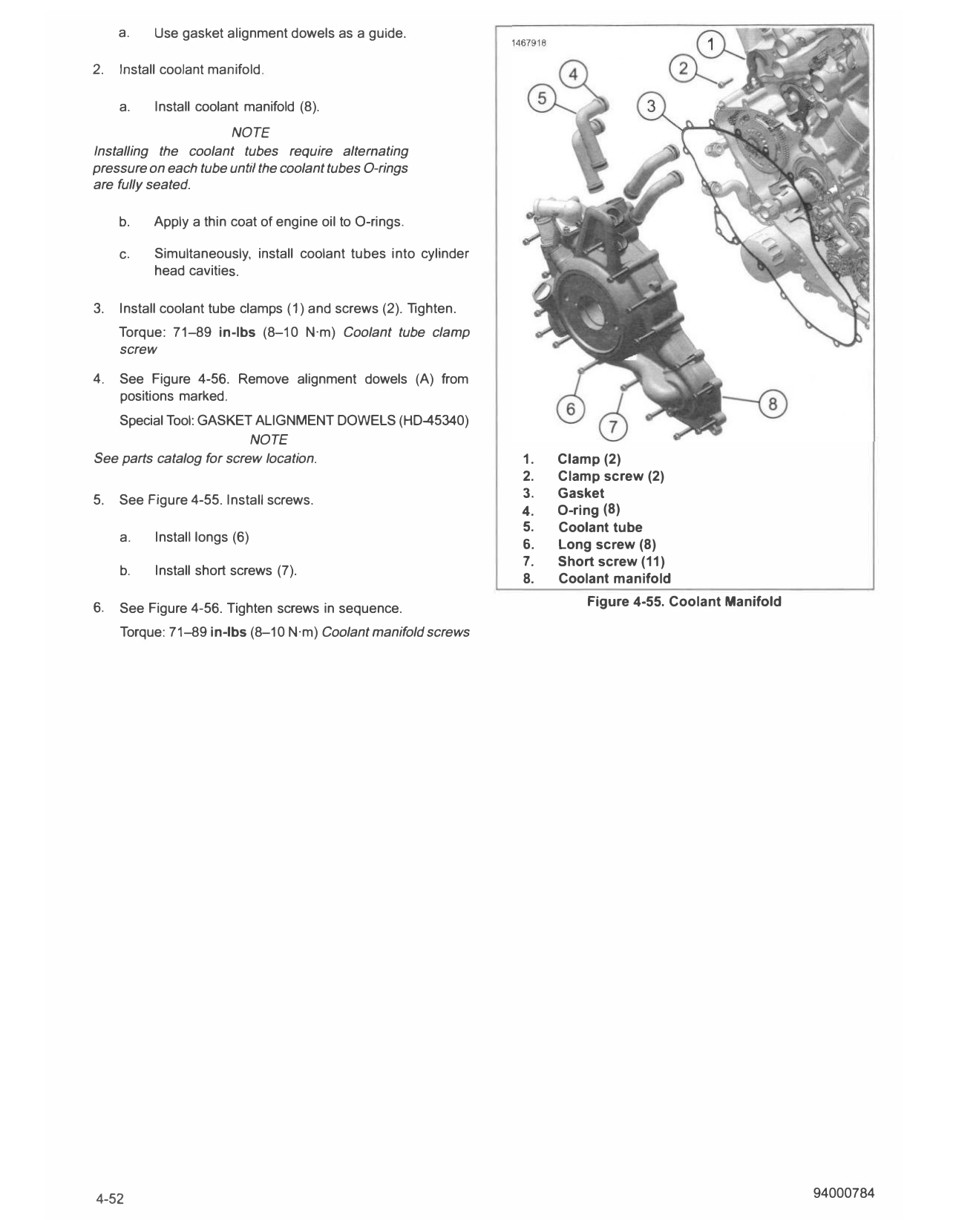
See parts catalog for screw location. 1. Clamp (2)
2. Clamp screw (2)
5. See Figure 4-55. Install screws. 3. Gasket
4. O-ring (8)
5. Coolant tube
a. Install longs (6)
6. Long screw (8)
7. Short screw (11)
b. Install short screws (7).
8. Coolant manifold
6. See Figure 4-56. T ighten screws in sequence. Figure 4-55. Coolant Manifold
Torque: 71-89 in-lbs (8-10 N·m) Coolant manifold screws
4-52 94000784
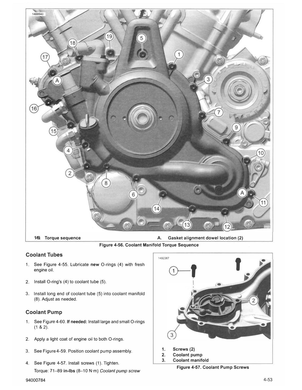
1-1!l Torque sequence A. Gasket alignment dowel location (2)
'
Figure 4-56. Coolant Manifold Torque Sequence
Coolant Tubes 1492367
0-f
1. See Figure 4-55. Lubricate new O-rings (4) with fresh
engine oil.
2. Install O-ring's (4) to coolant tube (5).
3. Install long end of coolant tube (5) into coolant manifold
(8). Adjust as needed.
Coolant Pump
1. See Figure 4-60. If needed: Install large and small O-rings
(1 & 2).
2. Apply a light coat of engine oil to both O-rings.
3. See Figure 4-59. Position coolant pump assembly. 1. Screws (2)
2. Coolant pump
3. Coolant manifold
4. See Figure 4-57. Install screws (1). Tighten.
Figure 4-57. Coolant Pump Screws
Torque: 71-89 in-lbs (8-10 N·m) Coolant pump screw
94000784 4-53
b. Route stator harness through grommet hole.
c. Set stator in coolant manifold.
2. See Figure 4-62. Install screws (1). Tighten.
Torque: 71-89 in-lbs (8--10 N·m) Stator to coolant manifold
screw
3. See Figure 4-61. Install stator harness (3) terminals (2)
into stator connector (1 ).
1492954
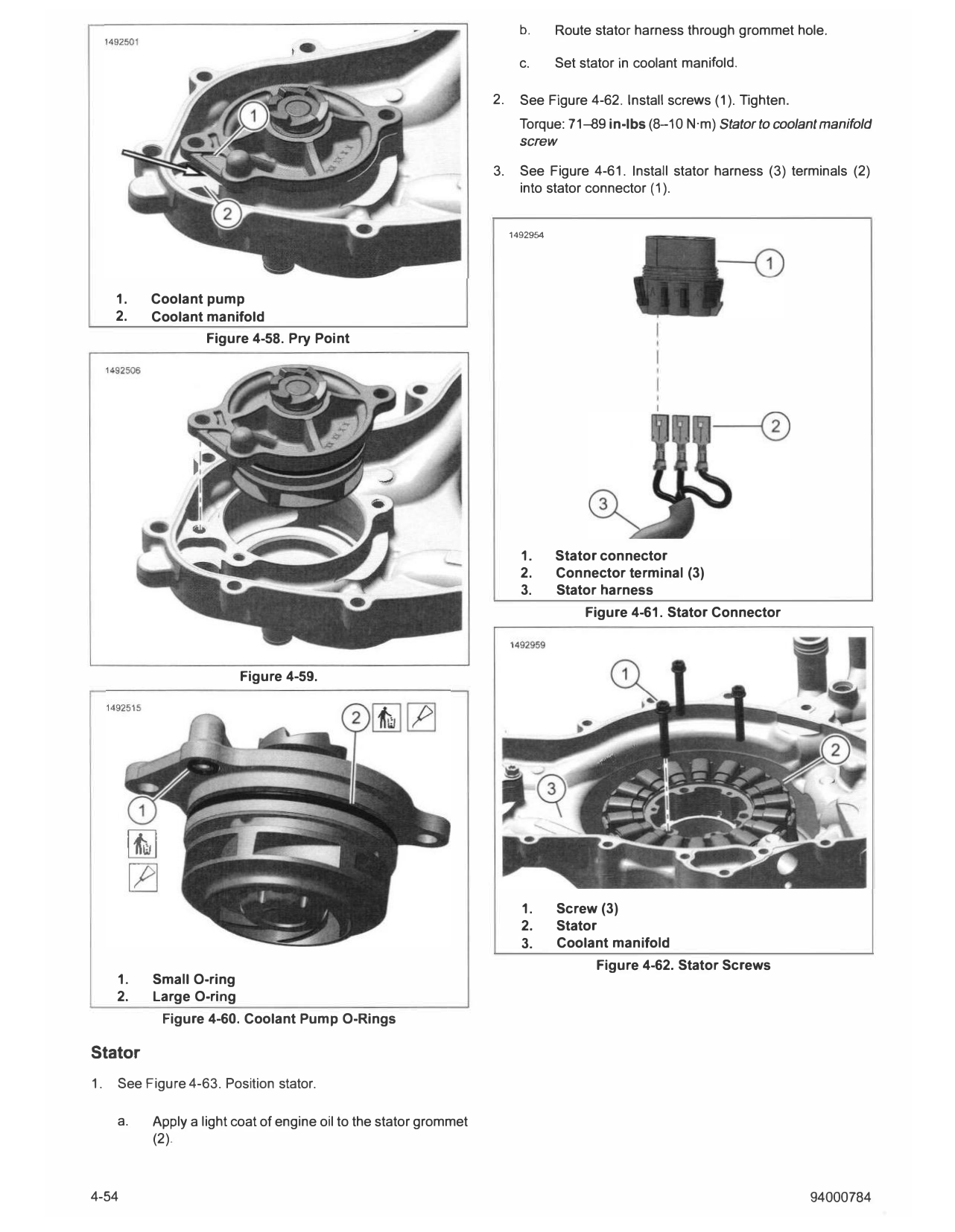
1. Coolant pump
2. Coolant manifold
Figure 4-58. Pry Point
1. Stator connector
2. Connector terminal (3)
3. Stator harness
Figure 4-61. Stator Connector
Figure 4-59.
1. Screw (3)
2. Stator
3. Coolant manifold
Figure 4-62. Stator Screws
1. Small O-ring
2. Large O-ring
Figure 4-60. Coolant Pump O-Rings
Stator
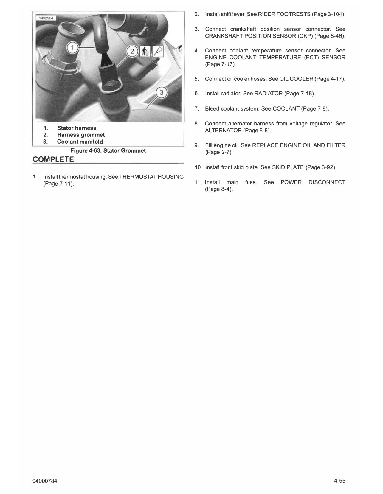
1. See Figure 4-63. Position stator.
a. Apply a light coat of engine oil to the stator grommet
(2).
4-54 94000784
2. Install shift lever. See RIDER FOOTRESTS (Page 3-104).
3. Connect crankshaft position sensor connector. See
CRANKSHAFT POSITION SENSOR (CKP) (Page 8-46).
4. Connect coolant temperature sensor connector. See
ENGINE COOLANT TEMPERATURE (ECT) SENSOR
(Page 7-17).
5. Connect oil cooler hoses. See OIL COOLER (Page 4-17).
6. Install radiator. See RADIATOR (Page 7-18).
7. Bleed coolant system. See COOLANT (Page 7-8).
8. Connect alternator harness from voltage regulator. See
1. Stator harness ALTERNATOR (Page 8-8).
2. Harness grommet
3. Coolant manifold
9. Fill engine oil. See REPLACE ENGINE OIL AND FILTER
Figure 4-63. Stator Grommet (Page 2-7).
COMPLETE
10. Install front skid plate. See SKID PLATE (Page 3-92).
1. Install thermostat housing. See THERMOSTAT HOUSING
(Page 7-11). 11. Install main fuse. See POWER DISCONNECT
(Page 8-4).
94000784 4-55