4.20 Pistons
Fragment manuala — str. 249–252
📋 Tekst do skopiowania (OCR/wyszukiwanie)
PISTONS 4.20
PREPARE
1. Cover cylinder opening to prevent piston pin circlip from
falling into crankcase.
NOTE
Abrasive particles can damage machined surfaces or plug oil 2. NOTE
passageways. Clean parts before disassembly to prevent
component damage. Use suitable tool to pry out circlip.
See Figure 4-47. Remove and discard piston pin circlip
1. Use low-pressure compressed air to clean exterior surfaces (2).
of engine.
3. Remove piston pin (1).
2. Remove main fuse. See POWER DISCONNECT
(Page 8-4).
4. Remove piston (3) from connecting rod (4).
3. Remove engine. See REPLACE ENGINE (Page 4-60).
INSTALL
4. Install crankshaft locking tool. See CRANKSHAFT
LOCKOUT (Page 4-18). CONSUMABLE PART NUMBER
SCREAM IN' 11300002
5. Remove primary cover and clutch baffle. See PRIMARY EAGLE
COVER (Page 4-49). ASSEMBLY LUBE
NOTICE
6. Remove camshaft timing sensors. See CAMSHAFT
TIMING SENSORS (Page 8-48). Handle piston with extreme care. The alloy used in these
pistons is very hard. Any scratches, gouges or other marks
7. Remove ignition coil. See IGNITION COIL (Page 8-16). in the pistons could score the cylinder during engine
operation and cause engine damage. (00546b)
8. Remove camshaft covers. See CAMSHAFT COVERS
(Page 4-21). 1. See Figure 4-47. Install piston pin circlip (2) on one side
of piston (3) with tang of circlip facing towards front of
9. Remove cylinder head covers. See CYLINDER HEAD piston as shown.
COVERS (Page 4-19).
a. Verify piston pin circlip (2) is fully seated in piston
10. Remove phaser solenoids with plate assembly. See pin boss.
PHASER SOLENOIDS (Page 4-22).
2. Apply lubricant to piston pin (1), piston pin bores and
11. Remove camshafts. See CAMSHAFTS AND PHASERS connecting rod bore.
(Page 4-38).
Consumable: SCREAMIN' EAGLE ASSEMBLY LUBE
(11300002)
12. Remove sprockets and timing chain. See CAMSHAFT
SPROCKET AND TIMING CHAIN (Page 4-24). 3. Position piston (3) on connecting rod (4) with the
Arrow/FRT markings on top of piston pointing toward front
13. Remove cylinder heads. See CYLINDER HEADS of engine.
(Page 4-34).
4. Insert piston pin (1) through piston pin bore and connecting
14. Remove cylinders. See CYLINDERS (Page 4-43). rod (4) until it contacts piston pin circlip (2) in opposite
piston pin boss.
REMOVE
5. Cover cylinder opening to prevent piston pin circlip (2) from
falling into crankcase.
NOTICE
Handle piston with extreme care. The alloy used in these 6. Install second piston pin circlip (2) with tang of circlip facing
pistons is very hard. Any scratches, gouges or other marks towards front of piston as shown.
in the pistons could score the cylinder during engine
operation and cause engine damage. (00546b) a. Verify piston pin circlip (2) is fully seated in piston
pin boss.
NOTE
Support the connecting rod (4) to prevent piston from striking
7. Verify smooth movement of piston (3) and piston pin (1)
crankcase. The rod cannot hit the crankcase due to the deck
on connecting rod (4).
height of the block. Protect connecting rod to prevent damage
while disassembled.
94000784 4-45
f. Verify that all oil holes are open and clean.
2. Thoroughly clean the three piston ring grooves of all carbon
deposits.
Inspect
1. Check piston running clearance.
NOTE
Pistons with superficial wear marks, minor scratching or
mild scoring are acceptable for use.
a. Insert a lightly oiled good piston pin into piston bore
to feel for proper fit. The pin should slide in and out
without binding, pivoting, or rocking.
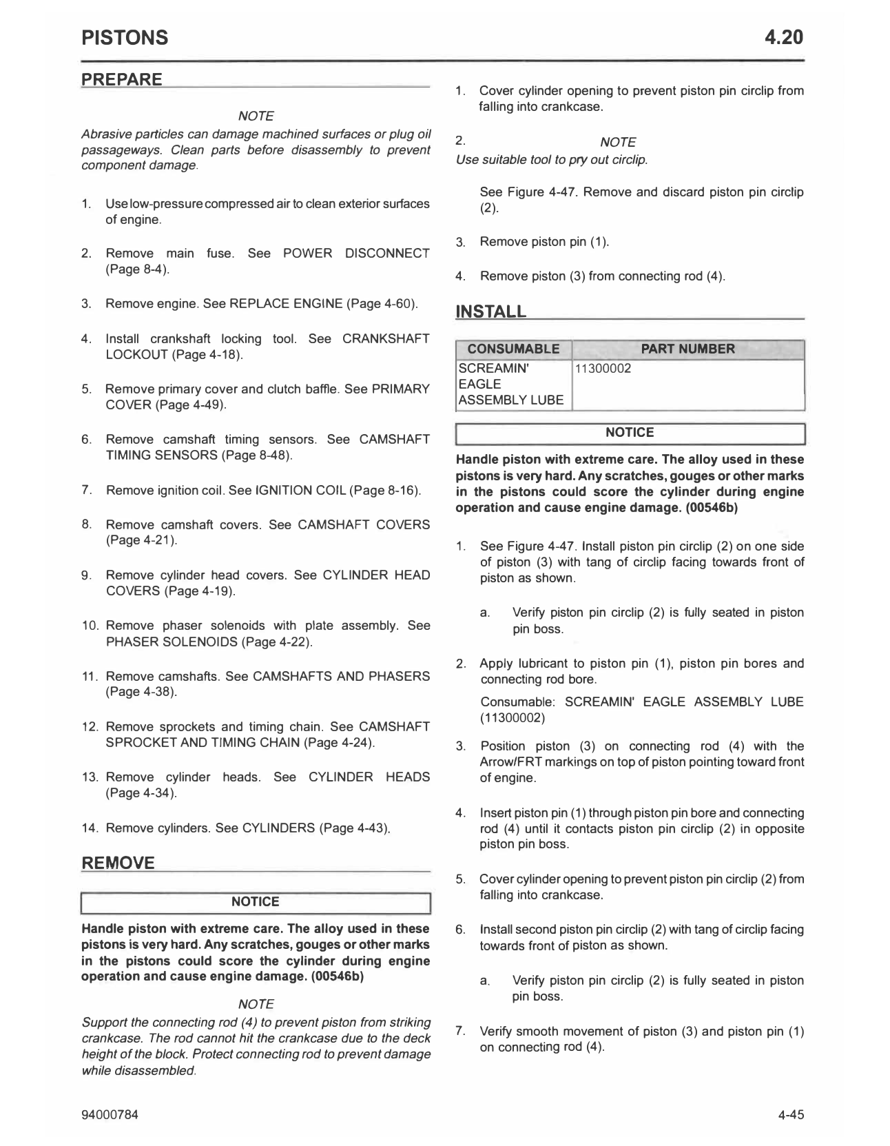
1. Piston pin b. Measure pin and pin bore diameters to determine
2. Piston pin circlip running clearance. Replace piston and/or pin if
3. Piston clearance exceeds specified dimension. See
4. Connecting rod SPECIFICATIONS (Page 4-3).
Figure 4-47.
DISASSEMBLE 2. Carefully inspect pistons for damage or excessive wear.
Discard if any following conditions are found:
1. Carefully remove piston rings from piston. Discard. NOTE
Thoroughly wash usable pistons to remove traces of dye.
CLEAN AND INSPECT
a. Using dye penetrant, inspect pistons for surface
Clean cracks. Particularly examine area around pin bores,
ring lands and oil drain holes beneath piston crown.
A WARNING
b. Cracked, worn or bent ring lands.
Compressed air can pierce the skin and flying debris from
compressed air could cause serious eye injury. Wear c. Cracks, gouges, deep scratches or heavy scoring.
safety glasses when working with compressed air. Never
use your hand to check for air leaks or to determine air d. Evidence of burning, etching or melting.
flow rates. (00061a)
e. Marks or imprints caused by contact with valves.
NOTE
• Do not sandblast or glass bead blast pistons. Bead blasting
3. Lightly file to remove any dings, nicks or burns around
rounds off ring lands.
edge of piston crown.
• Do not damage or enlarge holes.
• Do not use a wire brush to clean oil holes. 4. See Figure 4-48. Measure piston ring side clearance.
• Avoid scratching sides of piston ring grooves NOTE
Check piston clearance in the cylinder in which that piston
will run.
1. Clean piston.
• This inspection is very heat sensitive.
NOTE
A portion of a used compression ring properly ground to • Both piston and cylinder must be at room temperature
a sharp chisel-like edge works well to clean piston ring before proceeding.
grooves.
• The piston skirt coating has an oval shaped bare
aluminum opening (1) on each side of the piston for
a. Remove all combustion deposits. proper micrometer placement.
b. Soak pistons in hot water with dishwashing liquid or • Use a blade (2) or ball anvil (3) style micrometer to
a cleaner designed to remove carbon and does not measure piston.
corrode aluminum.
a. Insert edge of a new ring into piston ring groove.
c. Thoroughly rinse pistons.
b. Insert a feeler guage between upper surface of ring
d. Clean oil drain holes in oil control ring groove with a and ring land.
small bristle brush.
c. Repeat this check at several locations around piston.
e. Dry parts with low-pressure compressed air.
4-46 94000784
d. Discard piston if side clearance of either compression
sm08620
ring or oil control ring exceeds specified dimension.
See SPECIFICATIONS (Page 4-3).
5. Measure running clearance of pistons:
a. Measure piston skirt at bare aluminum openings (1).
b. Transfer measurement to dial bore gauge.
c. Measure cylinder bore at top and middle of piston
ring travel zone. Measure parallel and perpendicular
to crankshaft.
d. Replace piston and/or cylinder if running clearance
exceeds service wear limits. See SPECIFICATIONS
(Page 4-3).
-G)
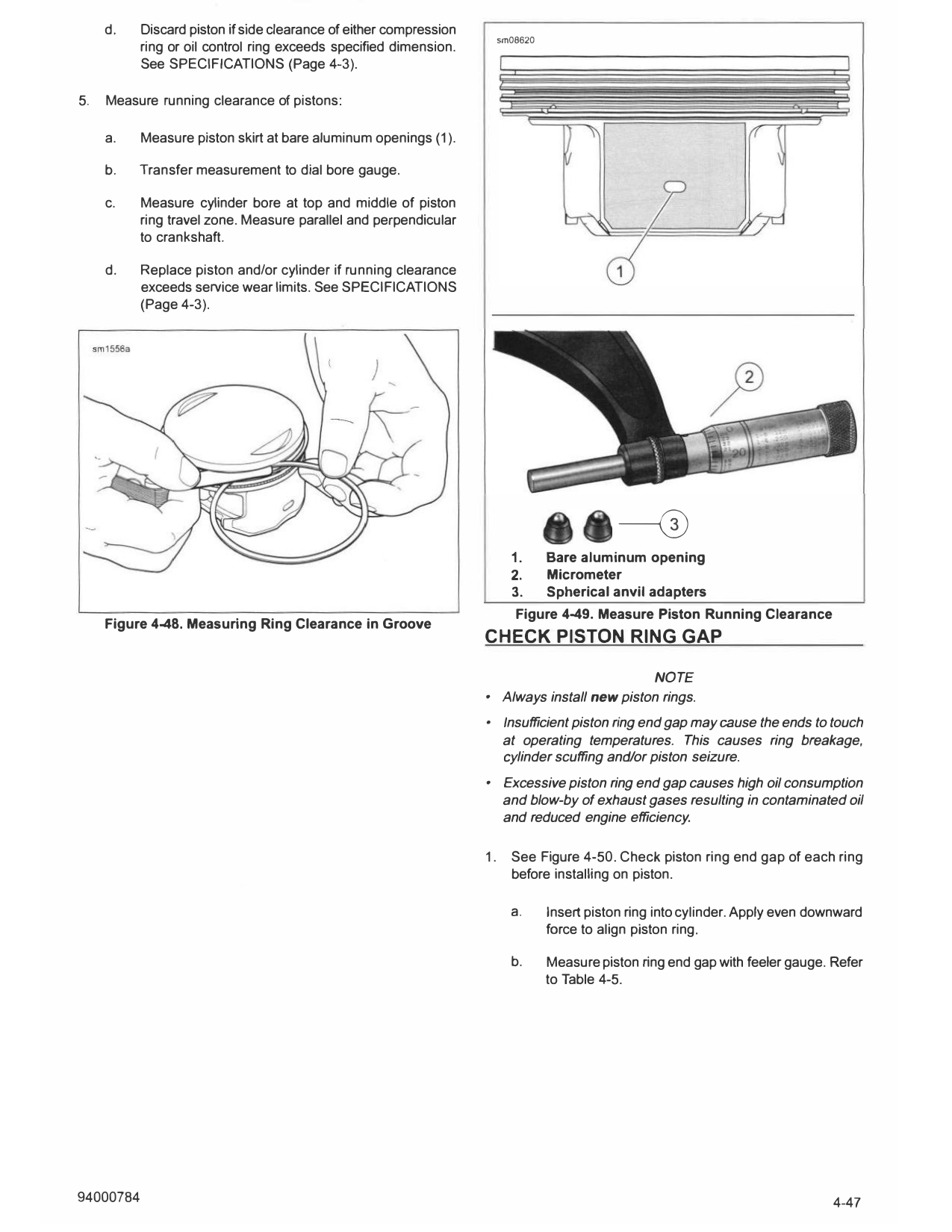
1. Bare aluminum opening
2. Micrometer
3. Spherical anvil adapters
Figure 4-49. Measure Piston Running Clearance
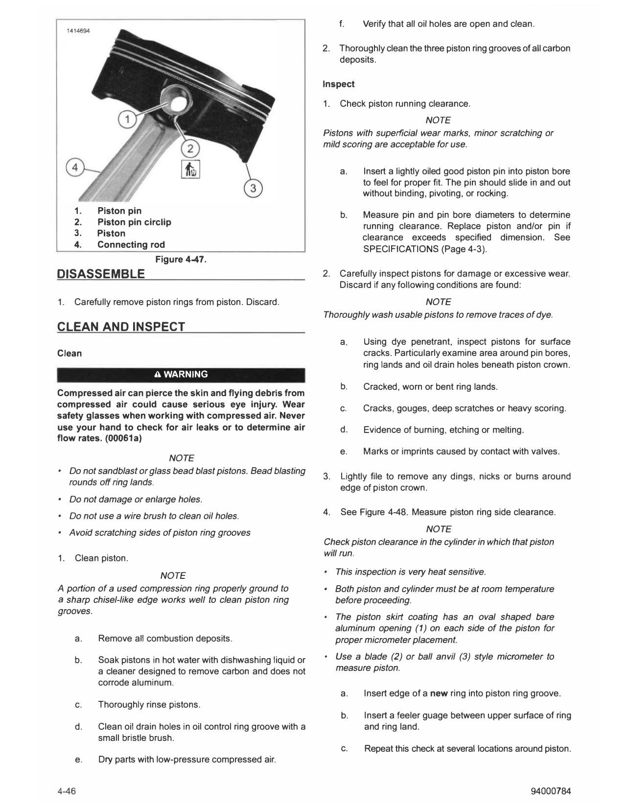
Figure 4-48. Measuring Ring Clearance in Groove
CHECK PISTON RING GAP
NOTE
• Always install new piston rings.
• Insufficient piston ring end gap may cause the ends to touch
at operating temperatures. This causes ring breakage,
cylinder scuffing and/or piston seizure.
• Excessive piston ring end gap causes high oil consumption
and blow-by of exhaust gases resulting in contaminated oil
and reduced engine efficiency.
1. See Figure 4-50. Check piston ring end gap of each ring
before installing on piston.
a. Insert piston ring into cylinder. Apply even downward
force to align piston ring.
b. Measure piston ring end gap with feeler gauge. Refer
to Table 4-5.
94000784 4-47
---
- 1415755
1
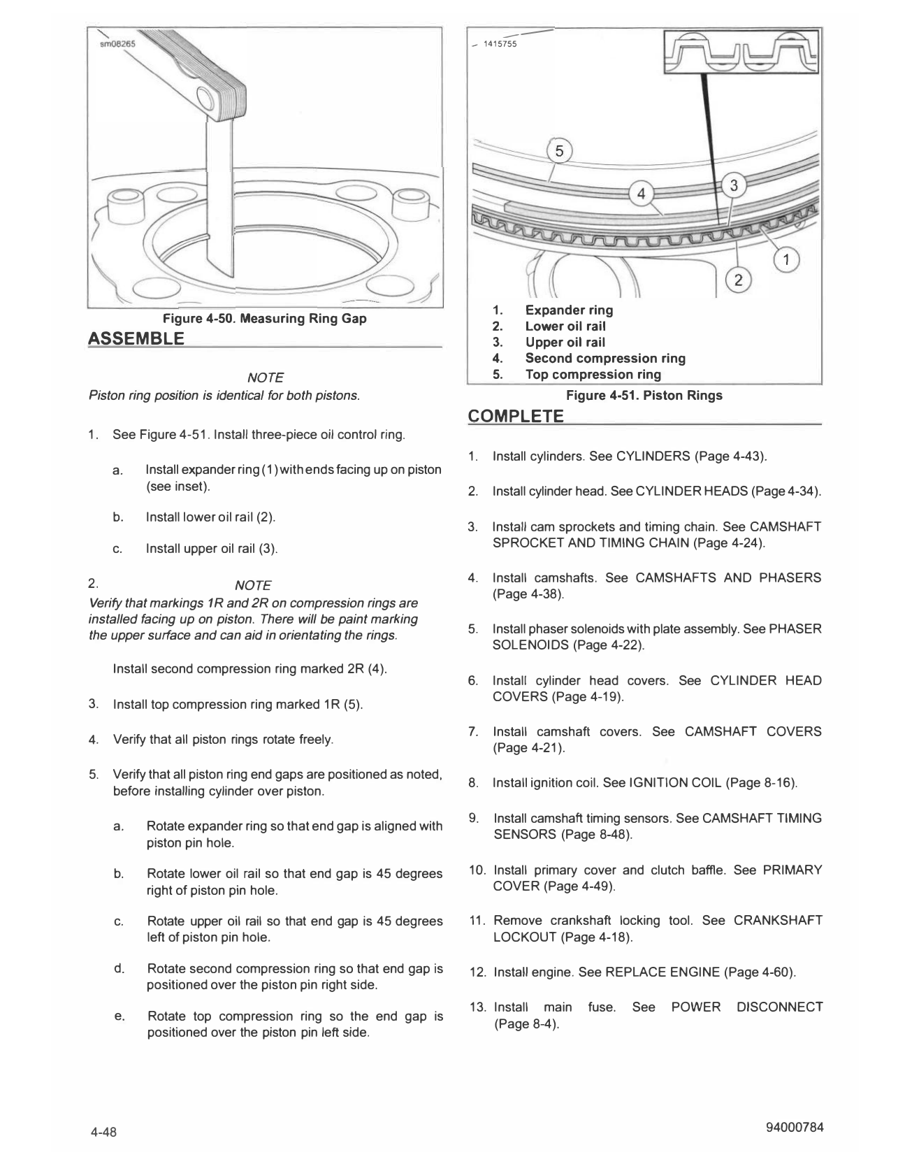
1. Expander ring
Figure 4-50. Measuring Ring Gap
2. Lower oil rail
ASSEMBLE 3. Upper oil rail
4. Second compression ring
NOTE 5. Top compression ring
Piston ring position is identical for both pistons. Figure 4-51. Piston Rings
COMPLETE
1. See Figure 4-51. Install three-piece oil control ring.
1. Install cylinders. See CYLINDERS (Page 4-43).
a. Install expander ring (1) with ends facing up on piston
(see inset). 2. Install cylinder head. See CYLINDER HEADS (Page 4-34).
b. Install lower oil rail (2).
3. Install cam sprockets and timing chain. See CAMSHAFT
c. Install upper oil rail (3). SPROCKET AND TIMING CHAIN (Page 4-24).
2. 4. Install camshafts. See CAMSHAFTS AND PHASERS
NOTE
(Page 4-38).
Verify that markings 1 R and 2R on compression rings are
installed facing up on piston. There will be paint marking
the upper surface and can aid in orientating the rings. 5. Install phaser solenoids with plate assembly. See PHASER
SOLENOIDS (Page 4-22).
Install second compression ring marked 2R (4).
6. Install cylinder head covers. See CYLINDER HEAD
COVERS (Page 4-19).
3. Install top compression ring marked 1R (5).
7. Install camshaft covers. See CAMSHAFT COVERS
4. Verify that all piston rings rotate freely.
(Page 4-21).
5. Verify that all piston ring end gaps are positioned as noted,
8. Install ignition coil. See IGNITION COIL (Page 8-16).
before installing cylinder over piston.
9. Install camshaft timing sensors. See CAMSHAFT TIMING
a. Rotate expander ring so that end gap is aligned with
SENSORS (Page 8-48).
piston pin hole.
b. Rotate lower oil rail so that end gap is 45 degrees 10. Install primary cover and clutch baffle. See PRIMARY
right of piston pin hole. COVER (Page 4-49).
c. Rotate upper oil rail so that end gap is 45 degrees 11. Remove crankshaft locking tool. See CRANKSHAFT
left of piston pin hole. LOCKOUT (Page 4-18).
d. Rotate second compression ring so that end gap is 12. Install engine. See REPLACE ENGINE (Page 4-60).
positioned over the piston pin right side.
13. Install main fuse. See POWER DISCONNECT
e. Rotate top compression ring so the end gap is
(Page 8-4).
positioned over the piston pin left side.
4-48 94000784