4.19 Cylinders
Fragment manuala — str. 247–248
📋 Tekst do skopiowania (OCR/wyszukiwanie)
CYLINDERS 4.19
PREPARE rotate crankshaft to position it at top dead center. The
crankshaft locking tool can only be installed with the rear
PART NUMBER TOOL NAME cylinder at top dead center. When working on the front cylinder
the locking tool will Just have to be removed.
HD-52956 CRANKSHAFT LOCKING TOOL
NOTE 1. NOTE
Abrasive particles can damage machined surfaces or plug oil The gasket should remain attached to bottom of cylinder
passageways. Clean parts before disassembly to prevent block for ease of installation.
component damage.
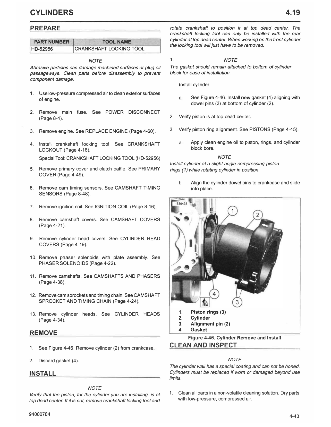
Install cylinder.
1. Use low-pressure compressed air to clean exterior surfaces
of engine. a. See Figure 4-46. Install new gasket (4) aligning with
dowel pins (3) at bottom of cylinder (2).
2. Remove main fuse. See POWER DISCONNECT
(Page 8-4). 2. Verify piston is at top dead center.
3. Remove engine. See REPLACE ENGINE (Page 4-60). 3. Verify piston ring alignment. See PISTONS (Page 4-45).
4. Install crankshaft locking tool. See CRANKSHAFT a. Apply clean engine oil to piston, rings, and cylinder
LOCKOUT (Page 4-18). block bore.
Special Tool: CRANKSHAFT LOCKING TOOL (HD-52956) NOTE
Install cylinder at a slight angle compressing piston
5. Remove primary cover and clutch baffle. See PRIMARY rings (1) while rotating cylinder in position.
COVER (Page 4-49).
b. Align the cylinder dowel pins to crankcase and slide
6. Remove cam timing sensors. See CAMSHAFT TIMING into place.
SENSORS (Page 8-48).
7. Remove ignition coil. See IGNITION COIL (Page 8-16).
8. Remove camshaft covers. See CAMSHAFT COVERS
(Page 4-21).
9. Remove cylinder head covers. See CYLINDER HEAD
COVERS (Page 4-19).
10. Remove phaser solenoids with plate assembly. See
PHASER SOLENOIDS (Page 4-22).
11. Remove camshafts. See CAMSHAFTS AND PHASERS
(Page 4-38).
12. Remove cam sprockets and timing chain. See CAMSHAFT
SPROCKET AND TIMING CHAIN (Page 4-24).
13. Remove cylinder heads. See CYLINDER HEADS 1. Piston rings (3)
(Page 4-34). 2. Cylinder
3. Alignment pin (2)
4. Gasket
REMOVE
Figure 4-46. Cylinder Remove and Install
1. See Figure 4-46. Remove cylinder (2) from crankcase. CLEAN AND INSPECT
2. Discard gasket (4). NOTE
The cylinder wall has a special coating and can not be honed.
INSTALL Cylinders must be replaced if worn or damaged beyond use
limits.
NOTE
Verify that the piston, for the cylinder you are installing, is at 1. Clean all parts in a non-volatile cleaning solution. Dry parts
top dead center. If it is not, remove crankshaft locking tool and with low-pressure, compressed air.
94000784 4-43
2. Inspect the cylinder bore for defects or damage in the 2. Install cam sprockets and timing chain. See CAMSHAFT
piston ring travel area. SPROCKET AND TIMING CHAIN (Page 4-24).
a. Inspect cylinder block for corrosion or cracking. 3. Install camshafts. See CAMSHAFTS AND PHASERS
(Page 4-38).
b. Cylinders with scratches shallower than the
crosshatch surface and shorter than the length of 4. Install phasers solenoids with plate assembly. See
piston travel are acceptable for use. PHASER SOLENOIDS (Page 4-22).
c. Run a fingernail across the scratches. If a scratch
5. Install cylinder head covers. See CYLINDER HEAD
catches a fingernail, cylinder must be replaced.
COVERS (Page 4-19).
d. Scoring or broad bands the length of piston travel,
or evidence material transferred between piston and 6. Install camshaft covers. See CAMSHAFT COVERS
cylinder, require cylinder replacement. (Page 4-21).
3. Carefully remove any nicks or burrs from machined gasket 7. Install ignition coil. See IGNITION COIL (Page 8-16).
surfaces.
8. Install camshaft timing sensors. See CAMSHAFT TIMING
4. Check gasket surfaces for flatness. Measure with a SENSORS (Page 8-48).
straightedge and feeler gauge.
9. Install primary cover and clutch baffle. See PRIMARY
5. Discard cylinder if either gasket surface flatness is not COVER (Page 4-49).
within wear limits. See SPECIFICATIONS (Page 4-3).
10. Remove crankshaft locking tool. See CRANKSHAFT
COMPLETE LOCKOUT (Page 4-18).
Special Tool: CRANKSHAFT LOCKING TOOL (HD-52956)
PART NUMBER TOOL NAME
11. Install engine. See REPLACE ENGINE (Page 4-60).
HD-52956 CRANKSHAFT LOCKING TOOL
1. Install cylinder heads. See CYLINDER HEADS 12. Install main fuse. See POWER DISCONNECT
(Page 4-34). (Page 8-4).