4.18 Camshafts And Phasers
Fragment manuala — str. 242–246
📋 Tekst do skopiowania (OCR/wyszukiwanie)
CAMSHAFTS AND PHASERS 4.18
PREPARE NOTE
Shift camshaft sideways to help with removal.
PART NUMBER TOOLNAME
HD-52956 CRANKSHAFT LOCKING TOOL 5. Remove intake and exhaust camshafts (5, 6).
1. Remove main fuse. See POWER DISCONNECT NOTE
(Page 8-4). Mark roller finger followers so they can be installed in the
same location and orientation.
2. Install crankshaft locking tool. See CRANKSHAFT
LOCKOUT (Page 4-18). 6. See Figure 4-42. Remove roller finger followers (1).
Special Tool: CRANKSHAFT LOCKING TOOL (HD-52956) NOTE
Mark lash adjusters so they can be installed in the same
a. Move radiator assembly to allow access to crankshaft
location and orientation.
lockout plug.
3. Front Camshaft: 7. Remove hydraulic lash adjusters (2).
a. Remove seat. See SEAT (Page 3-113). CLEAN AND INSPECT
b. Remove fuel tank. See FUEL TANK (Page 6-13). NOTE
Do not to remove the three screws to inspect the phaser. There
c. Remove airbox assembly. See AIR BOX is a special assembly process which can only be done at the
(Page 6-3). manufacturer. If the phaser has been disassembled, it will
render the phaser inoperative.
4. Rear Camshaft:
a. Remove seat. See SEAT (Page 3-113). Camshaft
1. Inspect lobes for abnormal wear or discoloration.
b. Remove fuel tank. See FUEL TANK (Page 6-13).
c. Remove cylinder head cover caddy. See CYLINDER 2. Inspect bearing surfaces for scoring or discoloration.
HEAD COVER CADDY (Page 8-60).
3. Measure bearing journals.
5. Remove camshaft timing sensors. See CAMSHAFT NOTE
TIMING SENSORS (Page 8-48). Remove and replace breather, air/oil separator only if
defective.
6. Remove ignition coil. See IGNITION COIL (Page 8-16).
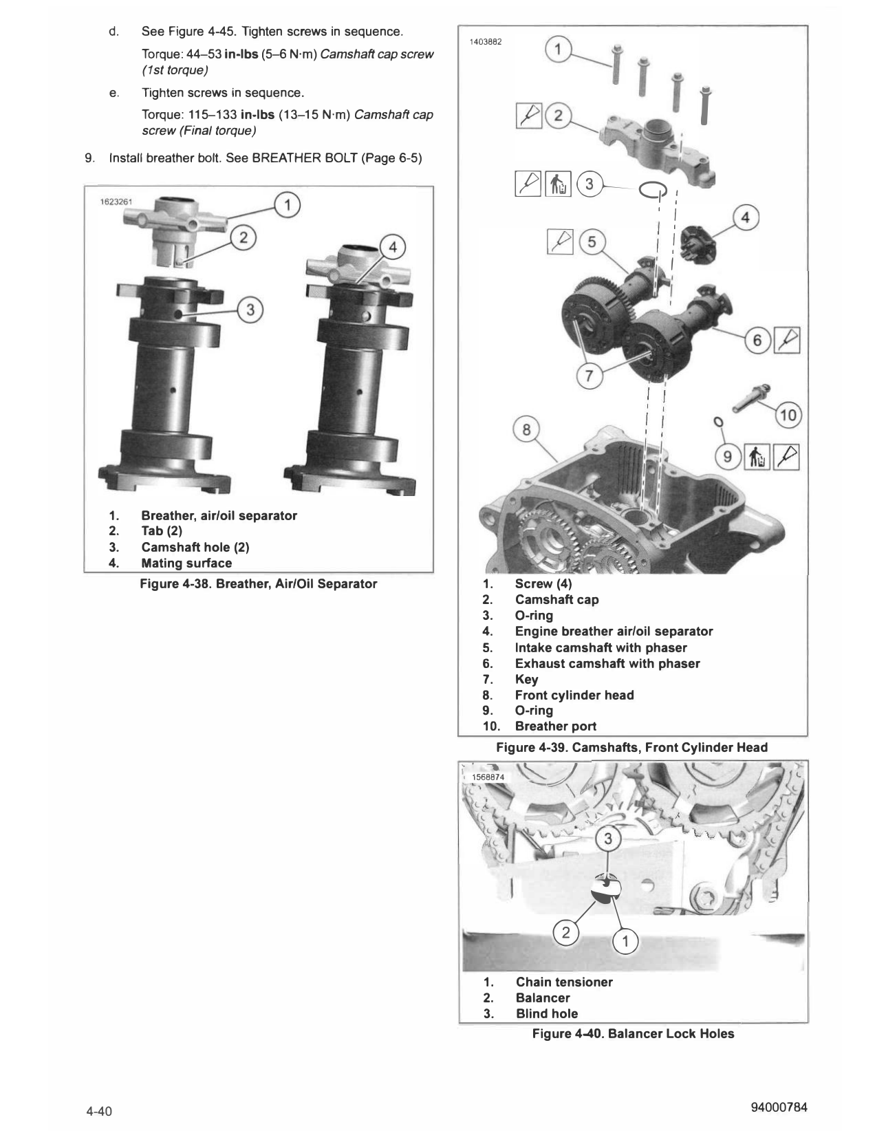
4. See Figure 4-39. Inspect breather, air/oil separator (4).
7. Remove camshaft cover. See CAMSHAFT COVERS
(Page 4-21).
Roller Finger Followers
8. Remove cylinder head covers. See CYLINDER HEAD
1. Clean all parts.
COVERS (Page 4-19).
2. Inspect for wear. Replace or repair as necessary.
9. Remove camshaft phasers with plate as an assembly. See
PHASER SOLENOIDS (Page 4-22).
a. Inspect roller for excessive wear.
10. Remove cam phaser center screw. See CAMSHAFT b. Inspect valve contact area for excessive wear.
SPROCKET AND TIMING CHAIN (Page 4-24).
c. Inspect lash adjuster pocket for excessive wear.
REMOVE
d. Verify that oil holes in roller finger followers are clean
and open.
1. Remove breather bolt. See BREATHER BOLT (Page 6-5)
2. See Figure 4-39. Remove screws (1). Gears
1. Clean parts in a non-volatile cleaning solution. Dry parts
3. Remove camshaft cap (2). with low-pressure, compressed air.
4. Remove and discard O-ring (3). 2. Replace components with worn or damaged gears.
INSTALL 4. Install breather on front intake cam.
PART NUMBER TOOL NAME a. See Figure 4-38. Align tabs (2) with camshaft holes
(3), install breather (1).
HD-42313 CAM CHAIN TENSIONER UNLOADER
b. Verify breather tabs engaged camshaft holes.
FASTENER TORQUE VALUE
Camshaft cap screw (1st 44-53 in-lbs 5-6 N·m C. Verify mating surfaces (4) are fully seated.
torque)
Camshaft cap screw (Final 115-133 in-lbs 13-15 N·m 5. See Figure 4-39. Install intake camshaft.
torque)
a. Lubricate camshaft journal.
CONSUMABLE PART NUMBER
SCREAMIN' 11300002 SCREAMIN' EAGLE ASSEMBLY LUBE (11300002)
EAGLE b. See Figure 4-43. Align timing mark (1) on cam
ASSEMBLY LUBE phaser (2) with drill spot face in cylinder head.
NOTE C. See Figure 4-39. Align key (7) in phaser with keyway
It is critical for initial start up of engine that the camshaft: lobes, in camshaft sprocket.
journals, and caps along with the hydraulic lash adjuster's and
roller finger followers be coated liberally with SCREAMIN' d. See Figure 4-44. Use alignment marks to position
EAGLE ASSEMBLY LUBE (11300002). Failure to do so will balancer gear.
result in catastrophic engine failure and contamination of oil
system. e. Install intake camshaft (5).
NOTE f. Make sure roller finger followers are in proper
If reinstalling the same hydraulic lash adjusters, place them in alignment with camshaft, lash adjusters and valves.
the same bore from which they were removed.
6. Install exhaust camshaft.
1. See Figure 4-42. Install pre-lubed hydraulic lash adjusters
(2). a. Lubricate camshaft journal.
Consumable: SCREAMIN' EAGLE ASSEMBLY LUBE SCREAMIN' EAGLE ASSEMBLY LUBE (11300002)
(11300002)
NOTE b. See Figure 4-43. Align timing mark (1) on cam
phaser (2) with drill spot face in cylinder head.
Roller finger followers are held in place by their own weight.
Make sure roller finger followers are installed in correct c. Align key (7) in phaser with keyway in camshaft
orientation. Failure to do so will result in catastrophic sprocket.
engine failure and contamination of oil system.
d. See Figure 4-39. Install exhaust camshaft (6).
2. See Figure 4-42. Install pre-lubed roller finger followers e. Make sure roller finger followers are in proper
(1 ). alignment with camshaft, lash adjusters and valves.
Consumable: SCREAMIN' EAGLE ASSEMBLY LUBE
(11300002) 7. Lubricate new O-ring (3) with fresh oil and install.
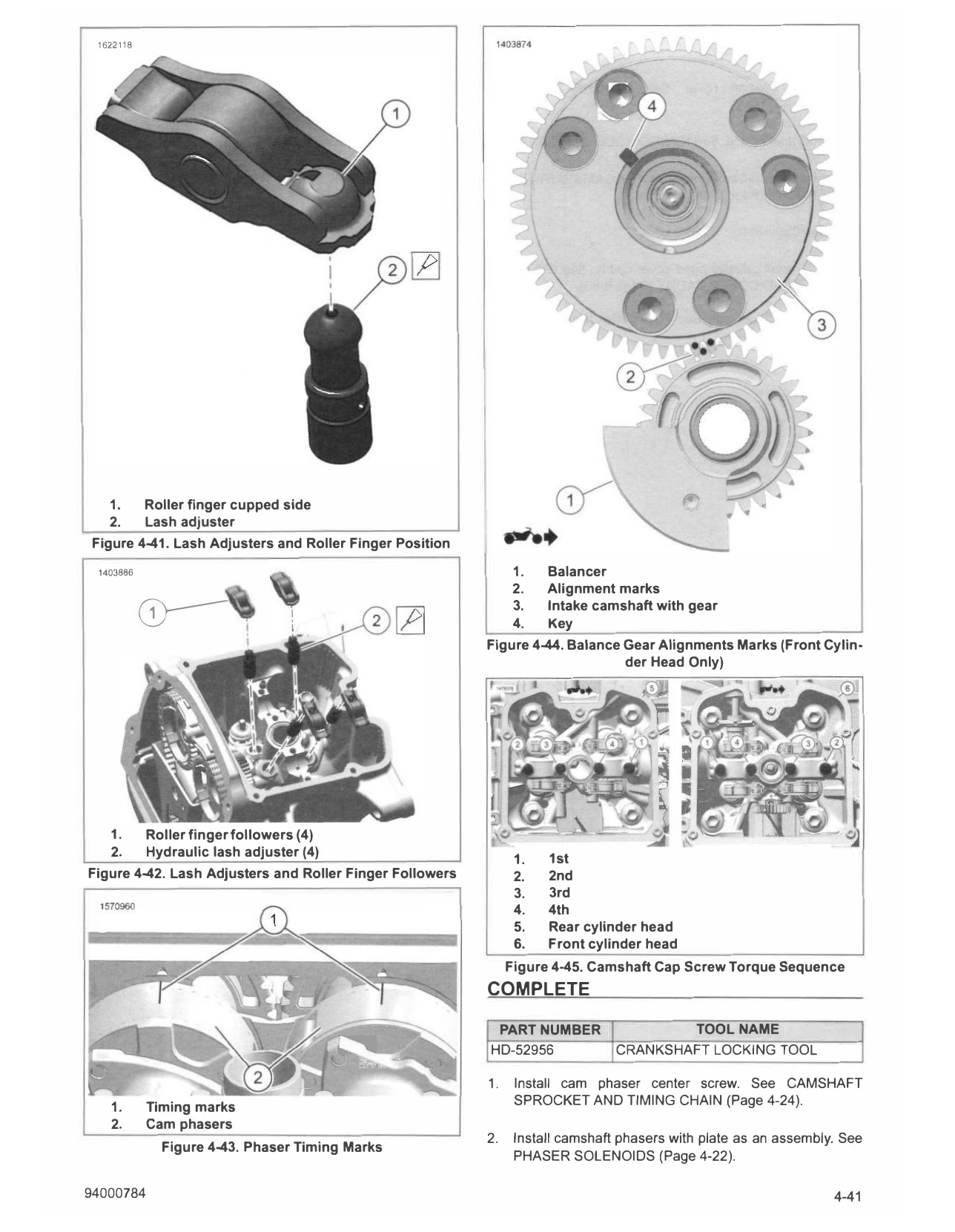
a. See Figure 4-41. Install roller finger followers with NOTE
flat side over valve and cupped side (1) over The camshaft may shift when trying to install the camshaft
hydraulic lash adjuster (2). cap. Make sure components have not become
disconnected or catastrophic failure will result.
3. See Figure 4-40. Install locking pin from unloader through
chain tensioner (1) into blind hole (3) to lock balancer (2). 8. Install camshaft cap.
Special Tool: CAM CHAIN TENSIONER UNLOADER NOTE
(HD-42313)
It is imperative to tighten the camshaft cap screws using
NOTE torque sequence shown.
Front cylinder head has an engine balancer assembly
The gear on balancer will have to be aligned with gear on
intake camshaft phaser. a. Lubricate cap journal.
Rear cylinder head is the same procedure minus alignment SCREAMIN' EAGLE ASSEMBLY LUBE (11300002)
of gears. b. See Figure 4-39. Install camshaft cap (2).
NOTE c. Install screws (1).
Breather is one time use, if not installed properly discard
and install a new breather.
94000784 4-39
d. See Figure 4-45. Tighten screws in sequence.
1403882
Torque: 44-53 in-lbs (5--6 N·m) Camshaft cap screw
(1st torque)
f
e. Tighten screws in sequence.
Torque: 115-133 in-lbs (13-15 N·m) Camshaft cap
screw (Final torque)
9. Install breather bolt. See BREATHER BOLT (Page 6-5)
[Z]�©-C?:
I
I I
I
I
I
1. Breather, air/oil separator
2. Tab (2)
3. Camshaft hole (2)
4. Mating surface
Figure 4-38. Breather, Air/Oil Separator 1. Screw (4)
2. Camshaft cap
3. O-ring
4. Engine breather air/oil separator
5. Intake camshaft with phaser
6. Exhaust camshaft with phaser
7. Key
8. Front cylinder head
9. O-ring
10. Breather port
Figure 4-39. Camshafts, Front Cylinder Head
1,. ""' "' I /,,
, 1568874 ''�
',�
,._,.,.,
1.
2.
ef\
Chain tensioner
Balancer
3. Blind hole
Figure 4-40. Balancer Lock Holes
4-40 94000784
1622118
1. Roller finger cupped side
2. Lash adjuster
Figure 4-41. Lash Adjusters and Roller Finger Position
1403886 1. Balancer
2. Alignment marks
3. Intake camshaft with gear
� 4. Key
Figure 4-44. Balance Gear Alignments Marks (Front Cylin
der Head Only)
1. Roller finger followers (4)
2. Hydraulic lash adjuster (4) 1st
1.
Figure 4-42. Lash Adjusters and Roller Finger Followers 2. 2nd
3. 3rd
4. 4th
5. Rear cylinder head
6. Front cylinder head
Figure 4-45. Camshaft Cap Screw Torque Sequence
COMPLETE
PART NUMBER TOOL NAME
HD-52956 CRANKSHAFT LOCKING TOOL
1. Install cam phaser center screw. See CAMSHAFT
SPROCKET AND TIMING CHAIN (Page 4-24).
1. Timing marks
2. Cam phasers
2. Install camshaft phasers with plate as an assembly. See
Figure 4-43. Phaser Timing Marks
PHASER SOLENOIDS (Page 4-22).
94000784 4-41
3. Install cylinder head cover. See CYLINDER HEAD c. Install seat. See SEAT (Page 3-113).
COVERS (Page 4-19).
8. Front Camshaft:
4. Install camshaft cover. See CAMSHAFT COVERS
(Page 4-21). a. Install airbox assembly. See AIR BOX (Page 6-3).
5. Install ignition coil. See IGNITION COIL (Page 8-16). b. Install fuel tank. See FUEL TANK (Page 6-13).
6. Install camshaft timing sensors. See CAMSHAFT TIMING c. Install seat. See SEAT (Page 3-113).
SENSORS (Page 8-48).
9. Remove crankshaft locking tool. See CRANKSHAFT
7. Rear Camshaft: LOCKO UT (Page 4-18).
Special Tool: CRANKSHAFT LOCKING TOOL (HD-52956)
a. Install cylinder head cover caddy. See CYLINDER
HEAD COVER CADDY (Page 8-60). 10. Install radiator assembly. See RADIATOR (Page 7-18).
b. Install fuel tank. See FUEL TANK (Page 6-13). 11. Install main fuse. See POWER DISCONNECT
(Page 8-4).
4-42 94000784