4.17 Cylinder Heads
Fragment manuala — str. 238–241
📋 Tekst do skopiowania (OCR/wyszukiwanie)
CYLINDER HEADS 4.17
PREPARE CLEAN
PART NUMBER TOOL NAME NOTE
HD-52956 CRANKSHAFT LOCKING TOOL Avoid getting debris in coolant and oil passages during gasket
removal and cleaning.
NOTE
Abrasive particles can damage machined surfaces or plug oil 1. Remove old gasket material from cylinder head. Do not
passageways. Clean parts before disassembly to prevent cause scratches or nicks.
component damage.
NOTE
Bead blasting materials could enter threaded holes. This
1. Use low-pressure compressed air to clean exterior surfaces
would adversely affect fastener engagement and torque
of engine.
indication. Cover all threaded holes before bead blasting.
2. Remove main fuse. See POWER DISCONNECT
(Page 8-4). NOTICE
Do not use glass or sand to bead blast surfaces exposed
3. Remove engine. See REPLACE ENGINE (Page 4-60). to engine oil. Blasting materials can lodge In pores of the
casting. Heat expansion releases this material which can
4. Install crankshaft locking tool. See CRANKSHAFT contaminate oil resulting in engine damage. (00534b)
LOCKOUT (Page 4-18).
Special Tool: CRANKSHAFT LOCKING TOOL (HD-52956) 2. Remove all carbon deposits from combustion chamber
and machined surfaces of cylinder head. Do not remove
5. Remove primary cover and clutch baffle. See PRIMARY any metal material.
COVER (Page 4-49).
3. To soften stubborn deposits, soak the cylinder head in a
6. Remove camshaft timing sensors. See CAMSHAFT chemical solution, such as GUNK HYDRO-SEAL or other
TIMING SENSORS (Page 8-48). carbon and gum dissolving agent. Repeat previous step
as necessary.
7. Remove ignition coil. See IGNITION COIL (Page 8-16).
NOTE
8. Remove camshaft cover. See CAMSHAFT COVERS Keep all parts grouped by location so they can be installed
(Page 4-21). in the original location.
9. Remove cylinder head cover. See CYLINDER HEAD 4. Thoroughly clean the cylinder head, spring retainers,
COVERS (Page 4-19). tapered keepers, valves and valve springs in a non-volatile
cleaning solution or solvent. Follow up with a thorough
10. Remove breather bolt. See BREATHER BOLT wash in hot soapy water.
(Page 6-5).
5. Thoroughly flush all coolant and oil passages to remove
11. Remove phaser solenoids with plate assembly. See loose debris.
PHASER SOLENOIDS (Page 4-22).
A WARNING
12. Remove camshafts. See CAMSHAFTS AND PHASERS
Compressed air can pierce the skin and flying debris from
(Page 4-38).
compressed air could cause serious eye injury. Wear
safety glasses when working with compressed air. Never
13. Remove sprockets and timing chain. See CAMSHAFT use your hand to check for air leaks or to determine air
SPROCKET AND TIMING CHAIN (Page 4-24). flow rates. (00061a)
REMOVE 6. Ory parts with low-pressure, compressed air.
1. See Figure 4-35. Remove cylinder head. 7. Clean threadlocker from all screws and threaded holes.
See Cleaning Fastener Threads in Cleaning (Page II).
a. Remove and discard screws (1).
a. Cover exposed internal engine area to prevent
b. Remove cylinder head (2). contamination from loosened threadlocker.
C. Discard gasket (3).
4-34 94000784
INSTALL
FASTENER TORQUE VALUE
Cylinder head screws torque 20-23 ft-lbs 27-31 N·m
step 1
Cylinder head screws torque -360 °
step 2
Cylinder head screws torque 15-18 ft-lbs 20-24 N·m
step 3
Cylinder head screws torque 35-38 ft-lbs 47.5--51.5 N·m
step 4
Cylinder head screws torque 148-155 °
step 5
1. Clean all gasket surfaces.
2. Thoroughly flush all coolant and oil passages to remove
loose debris.
3. See Figure 4-35. Install cylinder head.
NOTE
Screws (1) to be installed without lubricant.
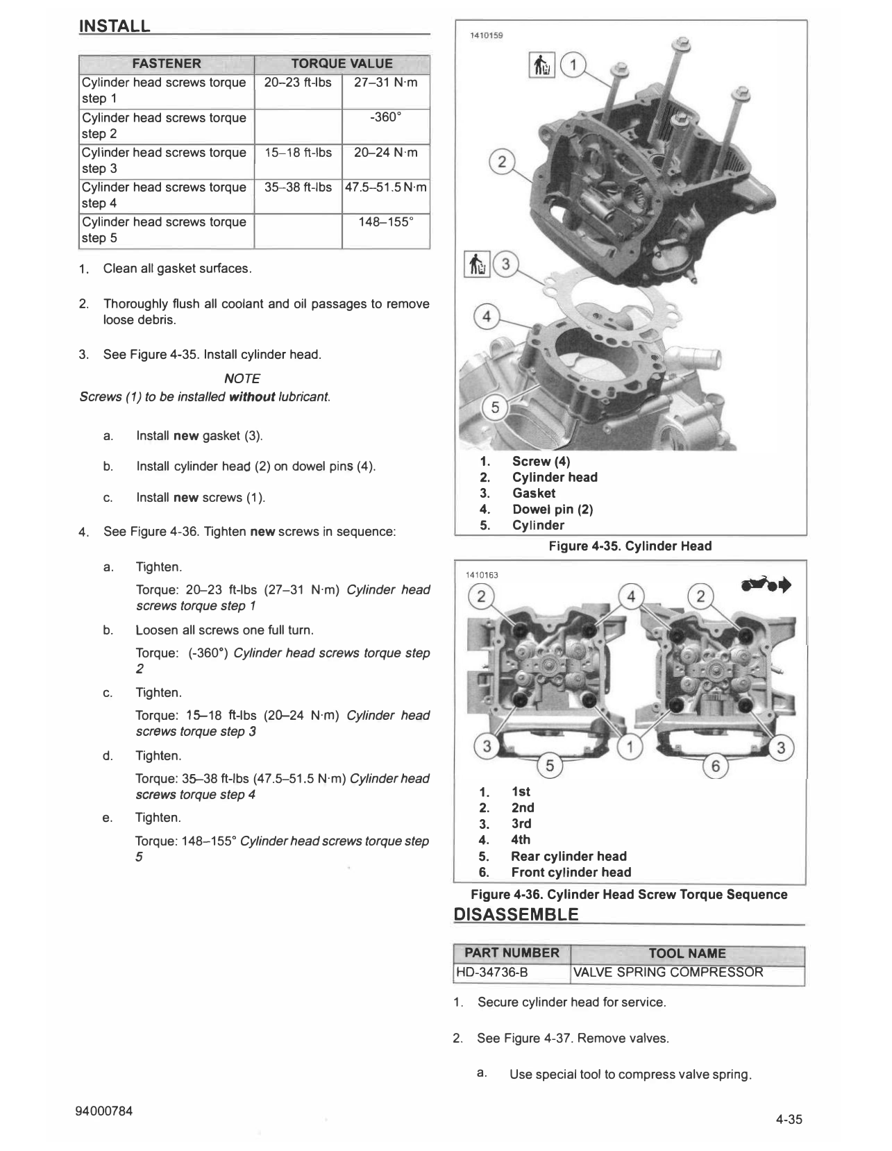
a. Install new gasket (3).
b. Install cylinder head (2) on dowel pins (4). 1. Screw (4)
2. Cylinder head
c. Install new screws (1 ). 3. Gasket
4. Dowel pin (2)
5. Cylinder
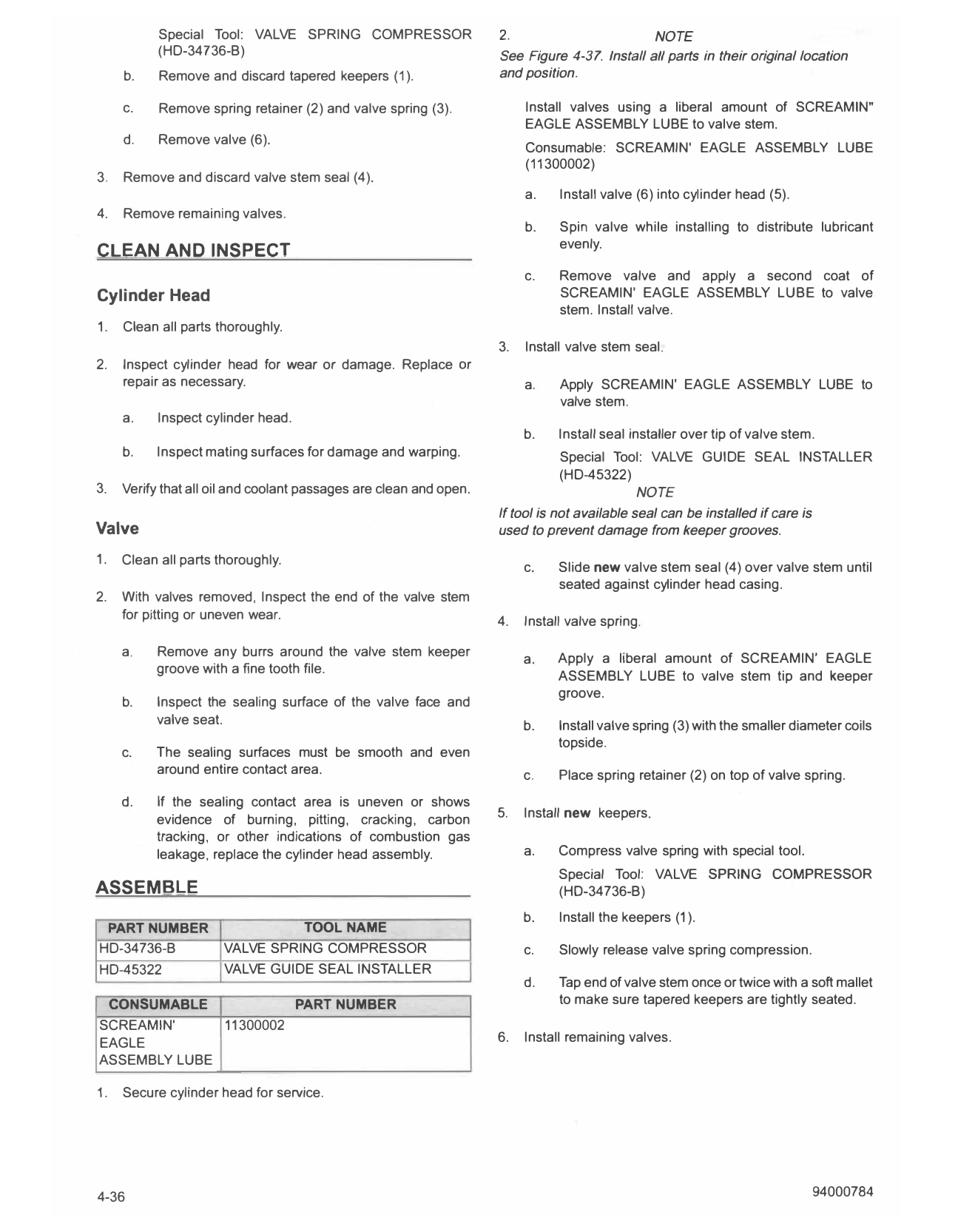
4. See Figure 4-36. Tighten new screws in sequence:
Figure 4-35. Cylinder Head
a. Tighten.
1410163
Torque: 20-23 ft-lbs (27-31 N·m) Cylinder head
screws torque step 1
b. Loosen all screws one full turn.
Torque: (-360 °) Cylinder head screws torque step
2
c. Tighten.
Torque: 15--18 ft-lbs (20-24 N·m) Cylinder head
screws torque step 3
d. Tighten.
Torque: 35--38 ft-lbs (47.5-51.5 N·m) Cylinder head
screws torque step 4 1. 1st
2. 2nd
e. Tighten. 3. 3rd
Torque: 148-155° Cylinder head screws torque step 4. 4th
5 5. Rear cylinder head
6. Front cylinder head
Figure 4-36. Cylinder Head Screw Torque Sequence
DISASSEMBLE
PART NUMBER T OOL NAME
HD-34736-B VALVE SPRING COMPRESSOR
1. Secure cylinder head for service.
2. See Figure 4-37. Remove valves.
a. Use special tool to compress valve spring.
Special Tool: VALVE SPRING COMPRESSOR 2. NOTE
(HD-34736-B) See Figure 4-31. Install all parts in their original location
b. Remove and discard tapered keepers (1). and position.
c. Remove spring retainer (2) and valve spring (3). Install valves using a liberal amount of SCREAMIN"
EAGLE ASSEMBLY LUBE to valve stem.
d. Remove valve (6).
Consumable: SCREAMIN' EAGLE ASSEMBLY LUBE
(11300002)
3. Remove and discard valve stem seal (4).
a. Install valve (6) into cylinder head (5).
4. Remove remaining valves.
b. Spin valve while installing to distribute lubricant
evenly.
CLEAN AND INSPECT
c. Remove valve and apply a second coat of
Cylinder Head SCREAMIN' EAGLE ASSEMBLY LUBE to valve
stem. Install valve.
1. Clean all parts thoroughly.
3. Install valve stem seal.
2. Inspect cylinder head for wear or damage. Replace or
repair as necessary. a. Apply SCREAMIN' EAGLE ASSEMBLY LUBE to
valve stem.
a. Inspect cylinder head.
b. Install seal installer over tip of valve stem.
b. Inspect mating surfaces for damage and warping. Special Tool: VALVE GUIDE SEAL INSTALLER
(HD-45322)
3. Verify that all oil and coolant passages are clean and open. NOTE
If tool is not available seal can be installed if care is
Valve used to prevent damage from keeper grooves.
1. Clean all parts thoroughly.
c. Slide new valve stem seal (4) over valve stem until
seated against cylinder head casing.
2. With valves removed, Inspect the end of the valve stem
for pitting or uneven wear. 4. Install valve spring.
a. Remove any burrs around the valve stem keeper
a. Apply a liberal amount of SCREAMIN' EAGLE
groove with a fine tooth file. ASSEMBLY LUBE to valve stem tip and keeper
groove.
b. Inspect the sealing surface of the valve face and
valve seat. b. Install valve spring (3) with the smaller diameter coils
topside.
c. T he sealing surfaces must be smooth and even
around entire contact area. c. Place spring retainer (2) on top of valve spring.
d. If the sealing contact area is uneven or shows
evidence of burning, pitting, cracking, carbon 5. Install new keepers.
tracking, or other indications of combustion gas
leakage, replace the cylinder head assembly. a. Compress valve spring with special tool.
Special Tool: VALVE SPRING COMPRESSOR
ASSEMBLE (H0-34736-B)
b. Install the keepers (1 ).
PART NUMBER TOOLNAME
HD-34736-B VALVE SPRING COMPRESSOR c. Slowly release valve spring compression.
HD-45322 VALVE GUIDE SEAL INSTALLER
d. Tap end of valve stem once or twice with a soft mallet
CONSUMABLE PART NUMBER to make sure tapered keepers are tightly seated.
SCREAM IN' 11300002
EAGLE 6. Install remaining valves.
ASSEMBLY LUBE
1. Secure cylinder head for service.
4-36 94000784
2. Install camshafts. See CAMSHAFTS AND PHASERS
(Page 4-38).
3. Install phaser solenoids with plate assembly. See PHASER
SOLENOIDS (Page 4-22).
4. Install breather bolt. See BREATHER BOLT (Page 6-5).
5. Install cylinder head cover. See CYLINDER HEAD
COVERS (Page 4-19).
6. Install camshaft cover. See CAMSHAFT COVERS
(Page 4-21).
7. Install ignition coil. See IGNITION COIL (Page 8-16).
8. Install camshaft timing sensors. See CAMSHAFT TIMING
SENSORS (Page 8-48).
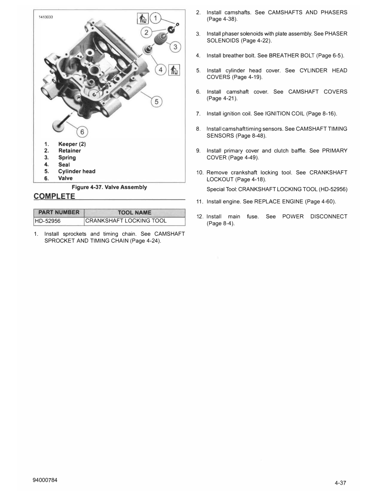
1. Keeper (2)
2. Retainer 9. Install primary cover and clutch baffle. See PRIMARY
3. Spring COVER (Page 4-49).
4. Seal
5. Cylinder head 10. Remove crankshaft locking tool. See CRANKSHAFT
6. Valve LOCKOUT (Page 4-18).
Figure 4-37. Valve Assembly Special Tool: CRANKSHAFT LOCKING TOOL (HD-52956)
COMPLETE
11. Install engine. See REPLACE ENGINE (Page 4-60).
PART NUMBER TOOL NAME
12. Install main fuse. See POWER DISCONNECT
HD-52956 CRANKSHAFT LOCKING TOOL (Page 8-4).
1. Install sprockets and timing chain. See CAMSHAFT
SPROCKET AND TIMING CHAIN (Page 4-24).