4.11 Crankshaft Lockout
Fragment manuala — str. 222
📋 Tekst do skopiowania (OCR/wyszukiwanie)
CRANKSHAFT LOCKOUT 4.11
CRANKSHAFT LOCKOUT 4. Install special tool (3) and hand tighten.
Special Tool: CRANKSHAFT LOCKING TOOL (HD-52956)
PART NUMBER TOOL NAME
HD-45314 CRANKSHAFT ROTATING WRENCH Unlock
HD-52956 CRANKSHAFT LOCKING TOOL 1. Remove special tool (3).
FASTENER TORQUE VALUE
2. Lubricate new O-ring (1) with fresh oil.
Crankcase locking tool access 97-115 in-lbs 11-13 N·m
I
plug
3. Install plug (2) with O-ring. Tighten.
Prepare Torque: 97-115 in-lbs (11-13 N·m) Crankcase locking
tool access plug
1. Remove main fuse. See POWER DISCONNECT
(Page 8-4).
2. Remove lower fairings. See FAIRING LOWERS
(Page 3-90).
3. Remove radiator mounting screws and position radiator
away from oil cooler. Support as needed. See RADIAT OR
(Page 7-18).
4. Remove outboard spark plugs. See INSPECT AND
REPLACE SPARK PLUGS (Page 2-41 ).
Lock
1. NOTE
Valves should be closed.
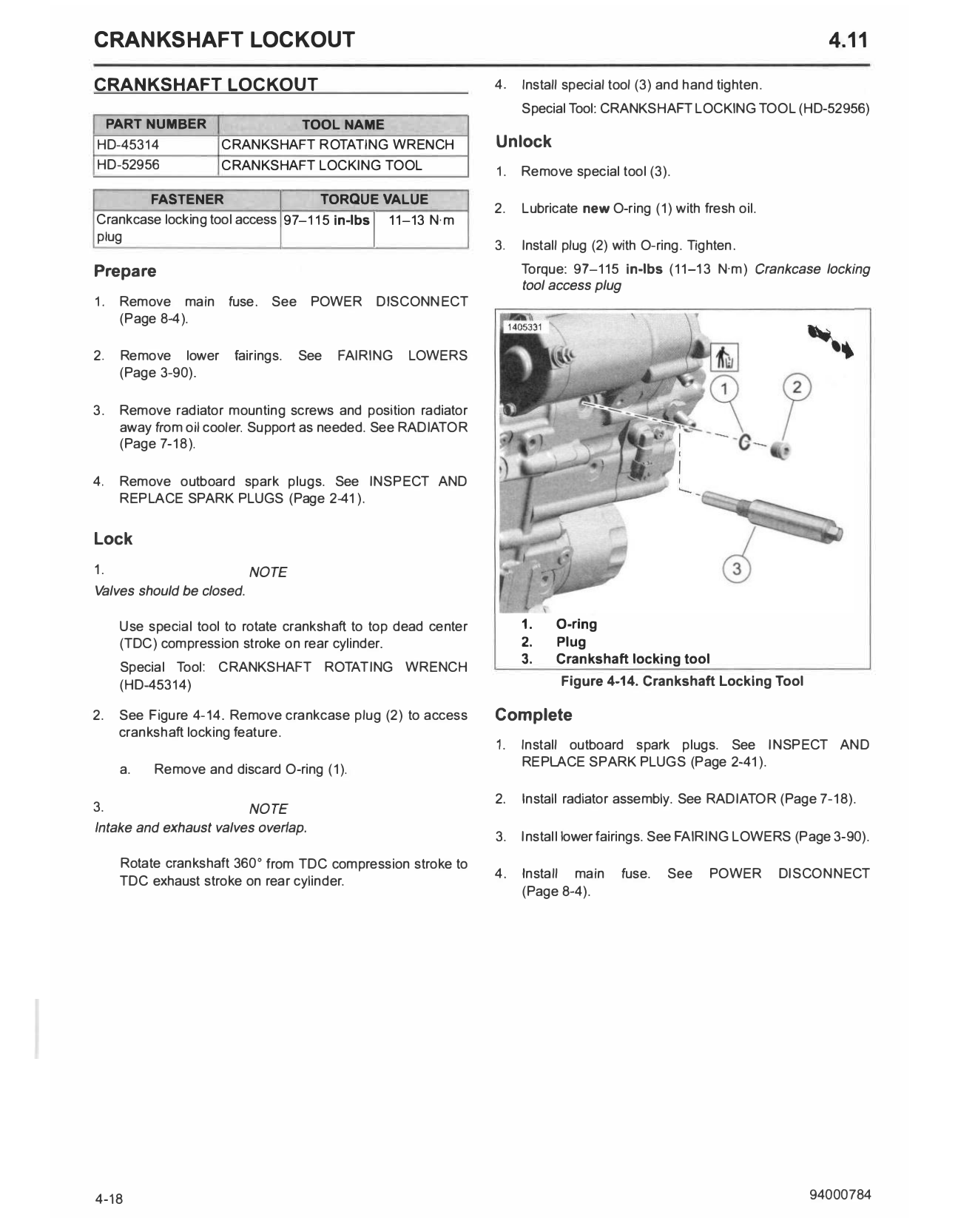
Use special tool to rotate crankshaft to top dead center 1. 0-ring
(T DC) compression stroke on rear cylinder. 2. Plug
3. Crankshaft locking tool
Special Tool: CRANKSHAFT ROTAT ING WRENCH
(HD-45314) Figure 4-14. Crankshaft Locking Tool
2. See Figure 4-14. Remove crankcase plug (2) to access Complete
crankshaft locking feature.
1. Install outboard spark plugs. See INSPECT AND
REPLACE SPARK PLUGS (Page 2-41 ).
a. Remove and discard O-ring (1).
2. Install radiator assembly. See RADIATOR (Page 7-18).
3. NOTE
Intake and exhaust valves overlap.
3. Install lower fairings. See FAIRING LOWERS (Page 3-90).
Rotate crankshaft 360 from TDC compression stroke to
°
T DC exhaust stroke on rear cylinder. 4. Install main fuse. See POWER DISCONNECT
(Page 8-4).
4-18 94000784