4.10 Oil Cooler
Fragment manuala — str. 221
📋 Tekst do skopiowania (OCR/wyszukiwanie)
OIL COOLER 4.10
PREPARE 2. Install oil cooler (2).
1. Remove main fuse. See POWER DISCONNECT 3. Install screws (1 ). Tighten.
(Page 8-4). Torque: 80-97 in-lbs (9-11 N·m) Oil cooler screws
2. Remove skid plate. See SKID PLATE (Page 3-92). Hose
3. If equipped: Remove lower fairings. See FAIRING 1. See Figure 4-13. Place new clamps (4, 7) on hoses (5,
LOWERS (Page 3-90). 6).
4. Remove radiator mounting screws and position radiator 2. Install hoses (5, 6).
away from oil cooler. Support as needed. See RADIATOR
(Page 7-18). 3. Secure clamps on hose ink marks using special tool. See
CRIMP CLAMPS (Page 4-16).
5. Remove battery tray. See BATTERY TRAY (Page 8-63).
REMOVE
Hose
NOTE
Use drain pan for residual coolant.
1. See Figure 4-13. Remove and discard clamps (4, 7).
2. Remove hose (5, 6).
Oil Cooler
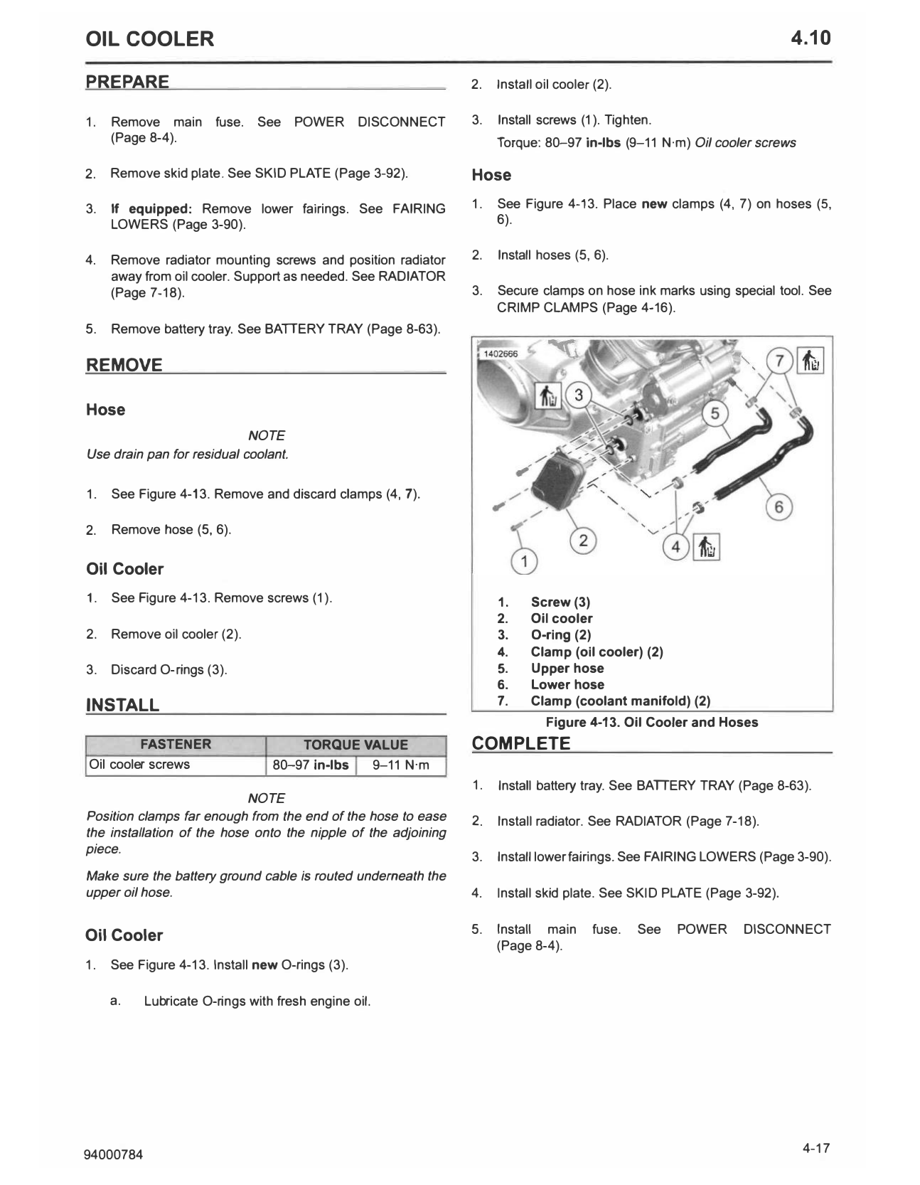
1. See Figure 4-13. Remove screws (1). 1. Screw (3)
2. Oil cooler
2. Remove oil cooler (2). 3. 0-ring (2)
4. Clamp (oil cooler) (2)
3. Discard O-rings (3). 5. Upper hose
6. Lower hose
INSTALL 7. Clamp (coolant manifold) (2)
Figure 4-13. Oil Cooler and Hoses
FASTENER TORQUE VALUE COMPLETE
Oil cooler screws 80-97 in-lbs 9-11 N·m
1. Install battery tray. See BATTERY TRAY (Page 8-63).
NOTE
Position clamps far enough from the end of the hose to ease 2. Install radiator. See RADIATOR (Page 7-18).
the installation of the hose onto the nipple of the adjoining
piece.
3. Install lower fairings. See FAIRING LOWERS (Page 3-90).
Make sure the battery ground cable is routed underneath the
upper oil hose. 4. Install skid plate. See SKID PLATE (Page 3-92).
5. Install main fuse. See POWER DISCONNECT
Oil Cooler
(Page 8-4).
1. See Figure 4-13. Install new O-rings (3).
a. Lubricate O-rings with fresh engine oil.
94000784 4-17