🏍️ PAN AMERICA SERWIS

3.5 Rear Wheel

Fragment manuala — str. 89–91

📋 Tekst do skopiowania (OCR/wyszukiwanie)
REAR WHEEL                                                                                                                    3.5
PREPARE                                                           INSTALL

1.    Raise rear of motorcycle. See Secure the Motorcycle for      CONSUMABLE                         PART NUMBER
      Service in GENERAL (Page 2-2).                              LOCTITE SILVER        11100001
                                                                  GRADE
2.    Inspect wheel bearings. See SEALED WHEEL BEARINGS           ANTI-SEIZE
      (Page 3-19).
                                                                  1.   See Figure 3-7. Install rear wheel
3.    Measure brake disc runout. See INSPECT BRAKES
      (Page 2-13).                                                     a.   Apply a light coat of anti-seize lubricant to rear axle
                                                                            (1 ), wheel bearing bores, and bore of wheel bearing
4.    Measure sprocket isolator wear. See INSPECT REAR                      spacer.
      SPROCKET ISOLATOR (Page 2-30).                                        LOCTITE SILVER GRADE ANTI-SEIZE (11100001)

5.    Remove line clip and P-clamps. See Brake Line: Rear              b.   Position rear wheel between rear fork.
      Caliper to ABS Module in BRAKE LINES (Page 3-40).
                                                                       C.   Install rear axle through axle adjuster (5), left leg of
                                                                            rear fork, and spacer (2).
6.    Release all drive chain tension. See INSPECT AND
      ADJUST DRIVE CHAIN AND SPROCKETS (Page 2-27).                    d.   Install rear axle through rear wheel.

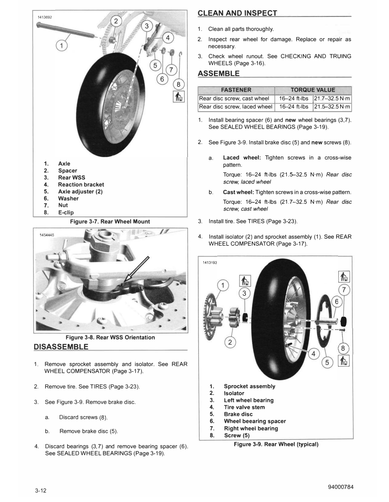
7.                     NOTE                                            e.   See Figure 3-8. Rotate WSS to position shown.
Do not operate brakes with caliper removed or caliper                       Verify wire harness is routed correctly.
pistons may be forced out. The caliper contains no
serviceable components and would require replacement.                  f.   See Figure 3-7. Install rear axle through rear wss
                                                                            (3), reaction bracket (4), right leg of rear fork and
      Detach rear brake caliper from reaction bracket. See REAR             axle adjuster (5).
      BRAKE CALIPER (Page 3-38).
                                                                       g.   Install washer (6).
REMOVE                                                                 h.   Install nut (7). Hand-tighten.

                          NOTE                                         i.   Install new E-clip (8).
• Never pull wheel speed sensor cable taut or use to retain
  wheel, axle or other components.                                     j.   Slide rear axle forward. Install drive chain on front
                                                                            and rear sprockets.
•    Keep wheel speed sensor and ABS encoder bearing away
     from magnetic fields.
                                                                  2.   Align rear wheel. See WHEEL ALIGNMENT (Page 3-27).

1.    See Figure 3-7. Remove axle.

      a.   Discard E-clip (8).

      b.   Remove nut (7).

      c.   Remove washer (6).

      d.   Release rear WSS wire from brake line.

     e.    Support wheel.

     f.    Remove axle. Catch rear WSS (3) and spacer (2).

2.   Remove chain from sprocket assembly.

3.                       NOTE
Hold sprocket to prevent it from dropping.

     Remove wheel.

 1413692
                                                              CLEAN AND INSPECT

                                                              1.     Clean all parts thoroughly.
                                                              2.     Inspect rear wheel for damage. Replace or repair as
                                                                     necessary.
                                                              3.     Check wheel runout. See CHECKING AND T RUING
                                                                     WHEELS (Page 3-16).
                                                              ASSEMBLE

                                                                      FASTENER                         TORQUE VALUE
                                                              Rear disc screw, cast wheel          16-24 ft-lbs 121.7-32.5 N·m
                                                              Rear disc screw, laced wheel         16-24 ft-lbs I2u�-32.5 N·m

                                                              1.     Install bearing spacer (6) and new wheel bearings (3,7).
                                                                     See SEALED WHEEL BEARINGS (Page 3-19).

                                                              2.     See Figure 3-9. Install brake disc (5) and new screws (8).

                                                                     a.      Laced wheel: Tighten screws in a cross-wise
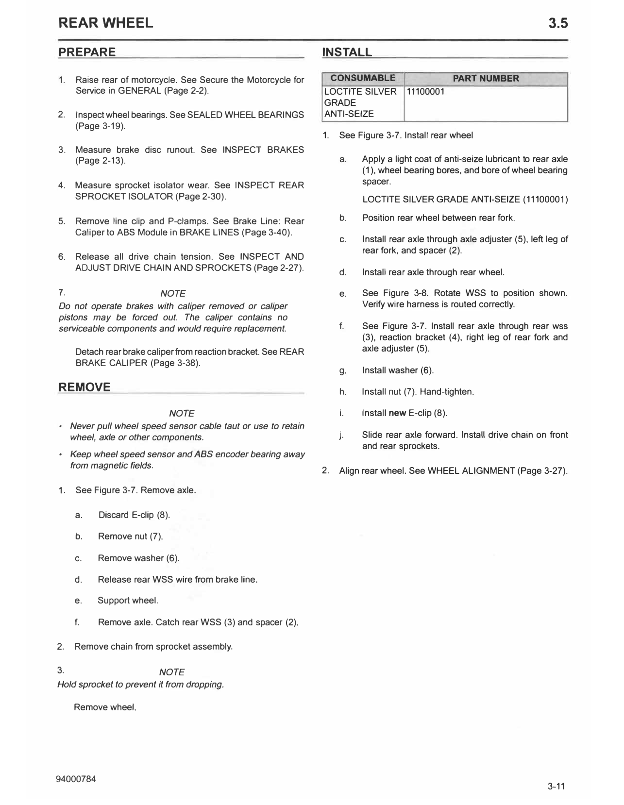
     1.    Axle                                                              pattern.
     2.    Spacer
                                                                             Torque: 16-24 ft-lbs (21.�32.5 N·m) Rear disc
     3.    RearWSS
     4.                                                                      screw, laced wheel
           Reaction bracket
     5.    Axle adjuster (2)                                         b.      Cast wheel: Tighten screws in a cross-wise pattern.
     6.    Washer
                                                                             Torque: 16-24 ft-lbs (21.7-32.5 N·m) Rear disc
     7.    Nut
                                                                             screw, cast wheel
     8.    E-clip
                Figure 3-7. RearWheel Mount                   3.     Install tire. See T IRES (Page 3-23).

                                                              4.     Install isolator (2) and sprocket assembly (1 ). See REAR
                                                                     WHEEL COMPENSATOR (Page 3-17).

                                                                   1413193

                                                                                                                          �

              Figure 3-8. RearWSS Orientation
                                                                                                                -��,
DISASSEMBLE                                                                                                                 8
                                                                                                                          �
1.   Remove sprocket assembly and isolator. See REAR
     WHEEL COMPENSATOR (Page 3-17).

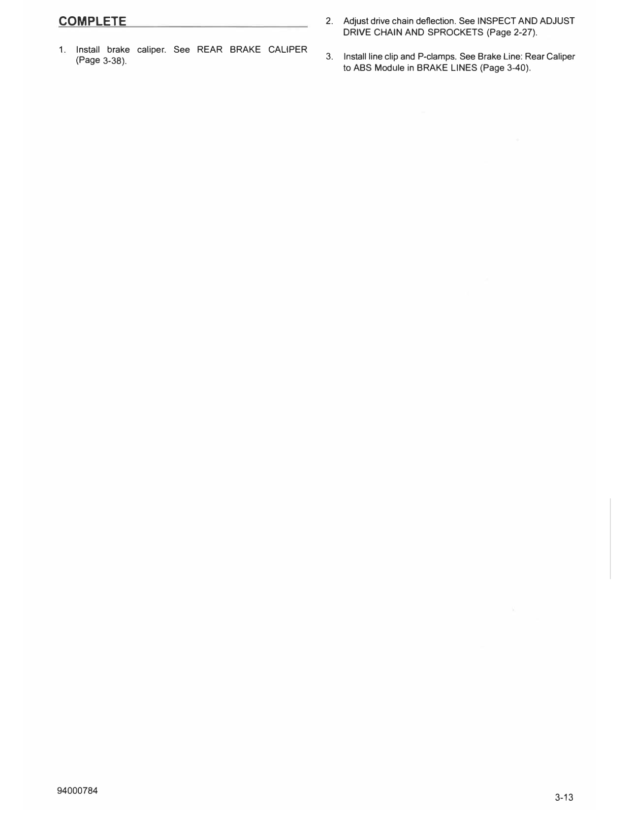
2.   Remove tire. See T IRES (Page 3-23).                             1.     Sprocket assembly
                                                                      2.     Isolator
3.   See Figure 3-9. Remove brake disc.                               3.     Left wheel bearing
                                                                      4.     Tire valve stem
                                                                      5.     Brake disc
     a.    Discard screws (8).
                                                                      6.     Wheel beearing spacer
                                                                      7.     Right wheel bearing
     b.     Remove brake disc (5).
                                                                      8.     Screw (5)
4.   Discard bearings (3, 7) and remove bearing spacer (6).                      Figure 3-9. Rear Wheel (typical)
     See SEALED WHEEL BEARINGS (Page 3-19).

COMPLETE                                             2.   Adjust drive chain deflection. See INSPECT AND ADJUST
                                                          DRIVE CHAIN AND SPROCKETS (Page 2-27).
1.   Install brake caliper. See REAR BRAKE CALIPER
     (Page 3-38).                                    3.   Install line clip and P-clamps. See Brake Line: Rear Caliper
                                                          to ABS Module in BRAKE LINES (Page 3-40).