3.4 Front Wheel
Fragment manuala — str. 86–88
📋 Tekst do skopiowania (OCR/wyszukiwanie)
FRONT WHEEL 3.4
PREPARE 2. Install brake calipers.
1. Raise front wheel. See Secure the Motorcycle for Service 3. Apply brake pressure.
in GENERAL (Page 2-2).
4. Tighten calipers.
2. Detach front brake caliper from fork. See FRONT BRAKE Torque: 28-38 ft-lbs (38-52 N·m) Brake caliper, front,
CALIPER (Page 3-32). mounting screw
REMOVE 5. Tighten front axle pinch screw.
Torque: 11-15 ft-lbs (15--20 N·m) Axle, front, pinch screw
NOTE
Never pull wheel speed sensor cable taut or use to retain 6. Release brake pressure.
wheel, axle or other components.
Keep wheel speed sensor and ABS encoder bearing away
from magnetic fields.
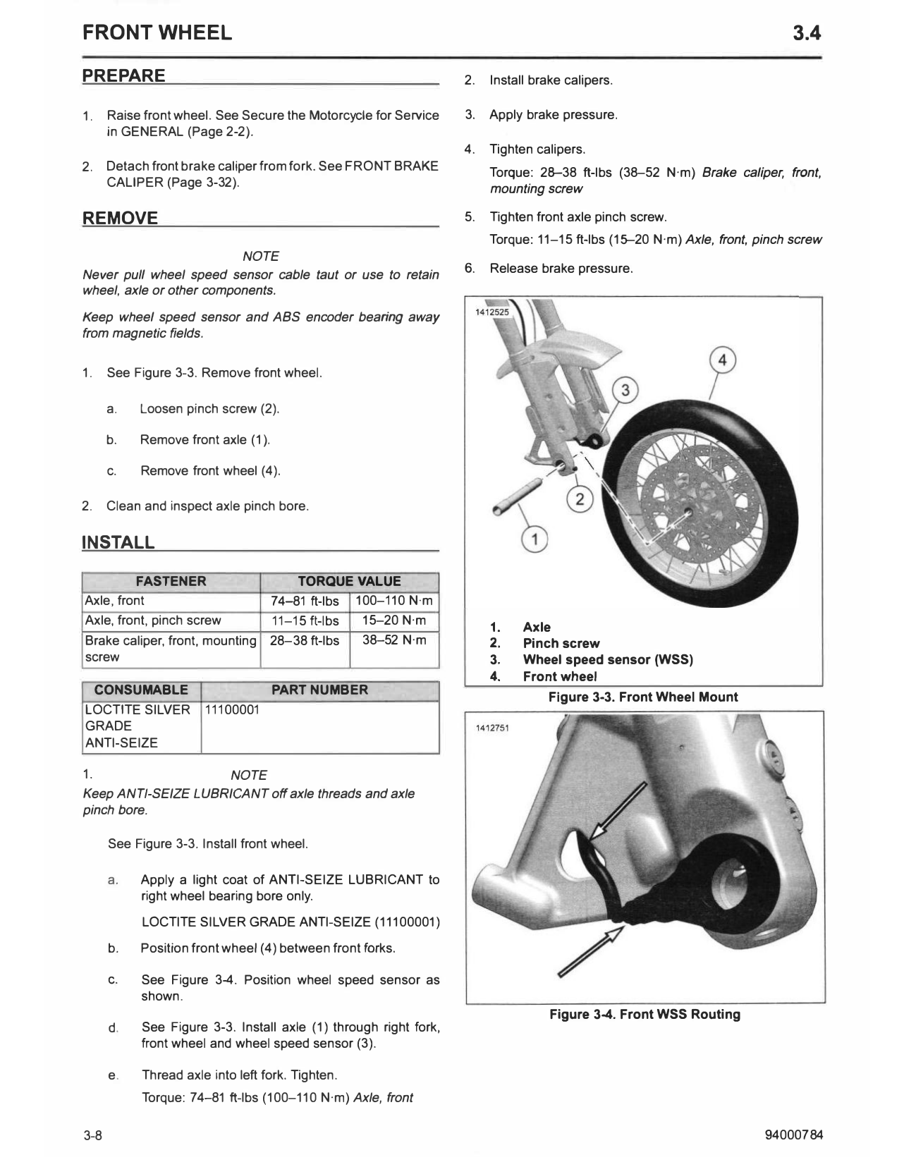
1. See Figure 3-3. Remove front wheel.
a. Loosen pinch screw (2).
b. Remove front axle (1).
c. Remove front wheel (4).
2. Clean and inspect axle pinch bore.
INSTALL
FASTENER TORQUE VALUE
Axle, front 74-81 ft-lbs 100-110 N·m
Axle, front, pinch screw 11-15 ft-lbs 15-20 N·m
1. Axle
Brake caliper, front, mounting 28-38 ft-lbs 38-52 N·m 2. Pinch screw
screw 3. Wheel speed sensor (WSS)
4. Front wheel
CONSUMABLE PART NUMBER
Figure 3-3. Front Wheel Mount
LOCTITE SILVER 11100001
GRADE
ANTI-SEIZE
1. NOTE
Keep ANTI-SEIZE LUBRICANT off axle threads and axle
pinch bore.
See Figure 3-3. Install front wheel.
a. Apply a light coat of ANTI-SEIZE LUBRICANT to
right wheel bearing bore only.
LOCTITE SILVER GRADE ANTI-SEIZE (11100001)
b. Position front wheel (4) between front forks.
c. See Figure 3-4. Position wheel speed sensor as
shown.
Figure 3-4. Front WSS Routing
d. See Figure 3-3. Install axle (1) through right fork,
front wheel and wheel speed sensor (3).
e. Thread axle into left fork. Tighten.
Torque: 74-81 ft-lbs (100-110 N·m) Axle, front
3-8 94000784
DISASSEMBLE 3. Install wheel bearing spacer (3) and new wheel bearings
(4,5). See SEALED WHEEL BEARINGS (Page 3-19).
Laced Wheel
NOTICE
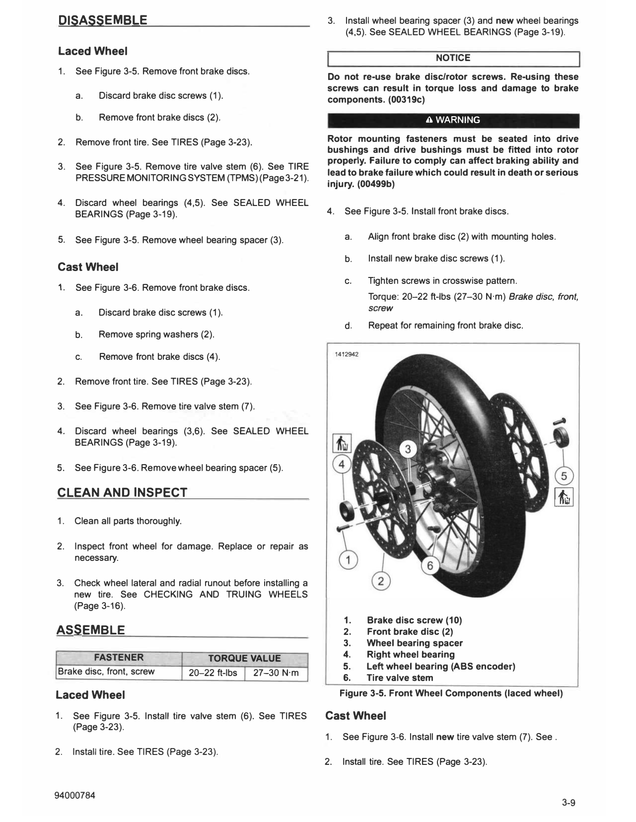
1. See Figure 3-5. Remove front brake discs.
Do not re-use brake disc/rotor screws. Re-using these
screws can result in torque loss and damage to brake
a. Discard brake disc screws (1). components. (00319c)
b. Remove front brake discs (2). A WARNING
2. Remove front tire. See TIRES (Page 3-23). Rotor mounting fasteners must be seated into drive
bushings and drive bushings must be fitted into rotor
properly. Failure to comply can affect braking ability and
3. See Figure 3-5. Remove tire valve stem (6). See TIRE
lead to brake failure which could result in death or serious
PRESSURE MONITORING SYSTEM (TPMS) (Page 3-21).
injury. (00499b)
4. Discard wheel bearings (4,5). See SEALED WHEEL
BEARINGS (Page 3-19). 4. See Figure 3-5. Install front brake discs.
5. See Figure 3-5. Remove wheel bearing spacer (3). a. Align front brake disc (2) with mounting holes.
b. Install new brake disc screws (1).
Cast Wheel
c. Tighten screws in crosswise pattern.
1. See Figure 3-6. Remove front brake discs.
Torque: 20-22 ft-lbs (27-30 N·m) Brake disc, front,
a. Discard brake disc screws (1). screw
d. Repeat for remaining front brake disc.
b. Remove spring washers (2).
c. Remove front brake discs (4).
2. Remove front tire. See TIRES (Page 3-23).
3. See Figure 3-6. Remove tire valve stem (7).
4. Discard wheel bearings (3,6). See SEALED WHEEL
BEARINGS (Page 3-19).
5. See Figure 3-6. Remove wheel bearing spacer (5).
CLEAN AND INSPECT
1. Clean all parts thoroughly.
2. Inspect front wheel for damage. Replace or repair as
necessary.
3. Check wheel lateral and radial runout before installing a
new tire. See CHECKING AND TRUING WHEELS
(Page 3-16).
1. Brake disc screw (10)
ASSEMBLE 2. Front brake disc (2)
3. Wheel bearing spacer
FASTENER TORQUE VALUE 4. Right wheel bearing
5. Left wheel bearing (ABS encoder)
Brake disc, front, screw 20-22 ft-lbs 27-30 N·m
6. Tire valve stem
Laced Wheel Figure 3-5. Front Wheel Components (laced wheel)
1. See Figure 3-5. Install tire valve stem (6). See TIRES Cast Wheel
(Page 3-23).
1. See Figure 3-6. Install new tire valve stem (7). See .
2. Install tire. See TIRES (Page 3-23).
2. Install tire. See TIRES (Page 3-23).
3. Install wheel bearing spacer (5) and new wheel bearings
(3,6). See SEALED WHEEL BEARINGS (Page 3-19).
NOTICE
Do not re-use brake disc/rotor screws. Re-using these
screws can result in torque loss and damage to brake
components. (00319c)
A WARNING
Rotor mounting fasteners must be seated into drive
bushings and drive bushings must be fitted into rotor
properly. Failure to comply can affect braking ability and
lead to brake failure which could result in death or serious
injury. (00499b)
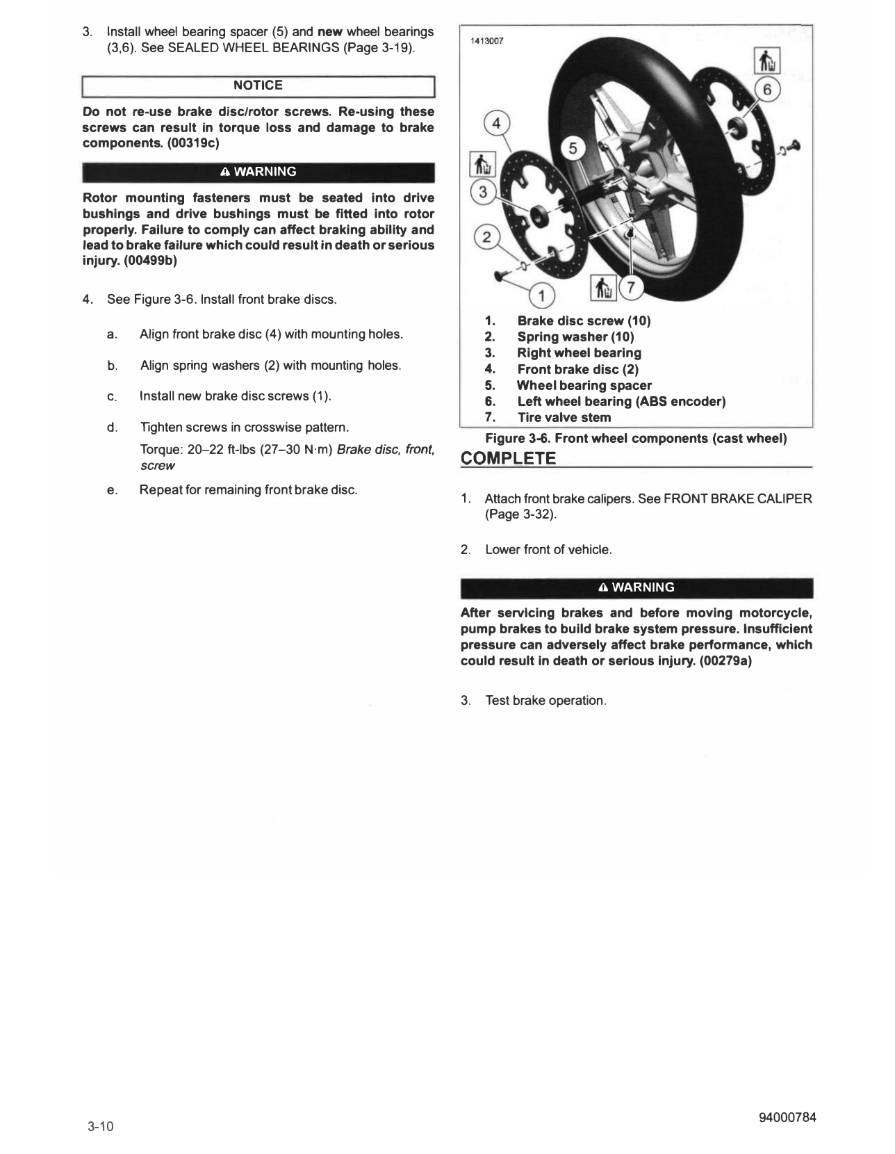
4. See Figure 3-6. Install front brake discs.
1. Brake disc screw (10)
a. Align front brake disc (4) with mounting holes. 2. Spring washer (10)
3. Right wheel bearing
b. Align spring washers (2) with mounting holes. 4. Front brake disc (2)
5. Wheel bearing spacer
c. Install new brake disc screws (1 ). 6. Left wheel bearing (ABS encoder)
7. Tire valve stem
d. Tighten screws in crosswise pattern.
Figure 3-6. Front wheel components (cast wheel)
Torque: 20-22 ft-lbs (27-30 N·m) Brake disc, front,
screw COMPLETE
e. Repeat for remaining front brake disc.
1. Attach front brake calipers. See FRONT BRAKE CALIPER
(Page 3-32).
2. Lower front of vehicle.
A WARNING
After servicing brakes and before moving motorcycle,
pump brakes to build brake system pressure. Insufficient
pressure can adversely affect brake performance, which
could result in death or serious injury. (00279a)
3. Test brake operation.