3.48 Frame
Fragment manuala — str. 196–200
📋 Tekst do skopiowania (OCR/wyszukiwanie)
FRAME 3.48
PREPARE 22. Remove steering head/fork stem and bracket, and front
fork assembly. See STEERING HEAD (Page 3-69).
Front Frame 23. Detach ignition coil bracket. See IGNITION COIL
1. Clamp rear wheel. (Page 8-16).
2. Remove skid plate. See SKID PLATE (Page 3-92). 24. Detach ECM bracket. See ELECTRONIC CONTROL
MODULE (ECM) (Page 8-38).
3. Install jack. See GENERAL (Page 2-2).
25. Detach radiator. See RADIATOR (Page 7-18).
4. Remove seat. See SEAT (Page 3-113).
26. Disconnect horn connectors. See HORN (Page 8-27).
5. Remove fairing. See FAIRING (Page 3-89).
27. Remove front electrical caddy. See FRONT ELECTRICAL
CADDY (Page 8-58).
6. Purge fuel line. See PURGE FUEL LINE (Page 6-9).
7. Remove fuel tank. See FUEL TANK (Page 6-13). Midframe
1. Remove middle side and right side steering head cover.
8. Remove steering head covers. See SIDE COVERS See SIDE COVERS (Page 3-52).
(Page 3-52).
2. Remove main fuse. See POWER DISCONNECT
9. Remove main fuse. See POWER DISCONNECT (Page 8-4).
(Page 8-4).
3. Remove seat. See SEAT (Page 3-113).
10. Remove cross-member. See FRAME CROSSMEMBER
(Page 3-123).
4. Detach under seat caddy. See UNDER SEAT CADDY
(Page 8-61).
11. If equipped: Remove engine guards. See ENGINE
GUARDS (Page 3-94).
5. Remove crossmember. See FRAME CROSSMEMBER
(Page 3-123).
12. If equipped: Remove headlight guard. See HEADLAMP
GUARD (Page 3-95).
6. Detach ABS module. See ABS MODULE (Page 3-46).
13. Remove fairing lowers. See FAIRING LOWERS
a. Remove ABS module frame cover.
(Page 3-90).
b. Detach ABS module.
14. Remove windshield and IM as an assembly. See COWL
(Page 3-86).
7. Remove front master cylinder to ABS module rear clamp.
See BRAKE LINES (Page 3-40).
15. Remove instrument module. See INSTRUMENT MODULE
(IM) (Page 8-24).
8. Detach rear brake master cylinder reservoir. See REAR
BRAKE MASTER CYLINDER (Page 3-34).
16. Remove headlamp and bracket assembly. See
HEADLAMP (Page 8-28).
9. Remove mufflers. See MUFFLERS (Page 6-35).
17. Remove steering damper and bracket assembly. See
10. Detach tail section. See TAIL SECTION (Page 3-114).
STEERING DAMPER ASSEMBLY (Page 3-72).
11. Remove center stand, if equipped. See CENTER STAND
18. Remove handlebar for service. See HANDLEBAR
(Page 3-111 ).
(Page 3-99).
12. Remove rider footrest brackets. See RIDER FOOTRESTS
19. Remove air box assembly. See AIR BOX (Page 6-3).
(Page 3-104).
20. Detach front brake lines from fender, steering head and
13. Remove chain guards. See CHAIN GUARDS (Page 3-76).
front frame. See BRAKE LINES (Page 3-40).
14. Remove rear brake line p-clamp from rear fork. See
21. Detach front calipers. See FRONT BRAKE CALIPER
BRAKE LINES (Page 3-40).
(Page 3-32).
15. Remove rear wheel. See REAR WHEEL (Page 3-11).
3-118 94000784
16. Remove rear fork. See REAR FORK (Page 3-74). 1577970
REMOVE
Front Frame
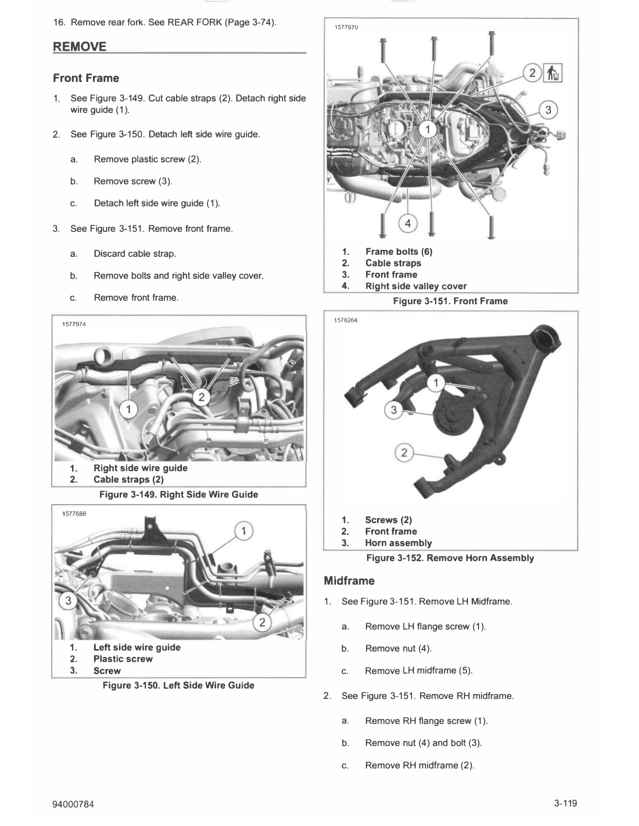
1. See Figure 3-149. Cut cable straps (2). Detach right side
wire guide (1 ).
2. See Figure 3-150. Detach left side wire guide.
a. Remove plastic screw (2).
b. Remove screw (3).
c. Detach left side wire guide (1 ).
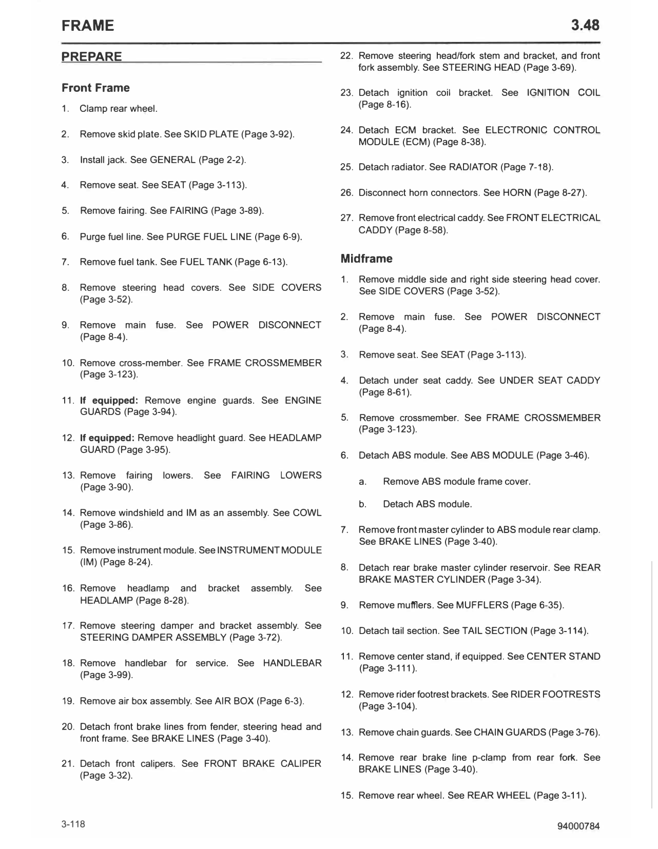
3. See Figure 3-151. Remove front frame.
a. Discard cable strap. 1. Frame bolts (6)
2. Cable straps
b. Remove bolts and right side valley cover. 3. Front frame
4. Right side valley cover
c. Remove front frame. Figure 3-151. Front Frame
1578264
1577974
1. Right side wire guide
2. Cable straps (2)
Figure 3-149. Right Side Wire Guide
1. Screws (2)
2. Front frame
3. Horn assembly
Figure 3-152. Remove Horn Assembly
Midframe
1. See Figure 3-151. Remove LH Midframe.
a. Remove LH flange screw (1 ).
1. Left side wire guide b. Remove nut (4).
2. Plastic screw
3. Screw c. Remove LH midframe (5).
Figure 3-150. Left Side Wire Guide
2. See Figure 3-151. Remove RH midframe.
a. Remove RH flange screw (1 ).
b. Remove nut (4) and bolt (3).
c. Remove RH midframe (2).
94000784 3-119
INSTALL
FASTENER TORQUE VALUE
Front frame bolts 80-88 ft-lbs 108-119 N·m
Horn screws 50-62 in-lbs 5.7-7 N·m
Left side cable guide screw 35-62 in-lbs 4-7 N·m
Midframe lower bolt and nut 80-88 ft-lbs 108-119 N·m
Midframe upper flange screws 125-137 ft-lbs 169-186 N·m
Front Frame
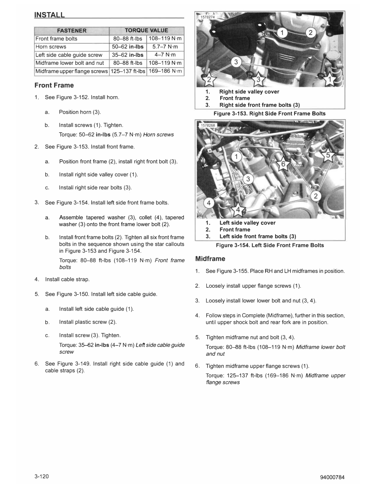
1. Right side valley cover
1. See Figure 3-152. Install horn. 2. Front frame
3. Right side front frame bolts (3)
a. Position horn (3). Figure 3-153. Right Side Front Frame Bolts
b. Install screws (1). Tighten.
Torque: 50-62 in-lbs (5.7-7 N·m) Horn screws
2. See Figure 3-153. Install front frame.
a. Position front frame (2), install right front bolt (3).
b. Install right side valley cover (1).
c. Install right side rear bolts (3).
3. See Figure 3-154. Install left side front frame bolts.
a. Assemble tapered washer (3), collet (4), tapered
washer (3) onto the front frame lower bolt (2). 1. Left side valley cover
2. Front frame
b. Install front frame bolts (2). Tighten all six front frame 3. Left side front frame bolts (3)
bolts in the sequence shown using the star callouts Figure 3-154. Left Side Front Frame Bolts
in Figure 3-153 and Figure 3-154.
Torque: 80-88 ft-lbs (108-119 N·m} Front frame Midframe
bolts
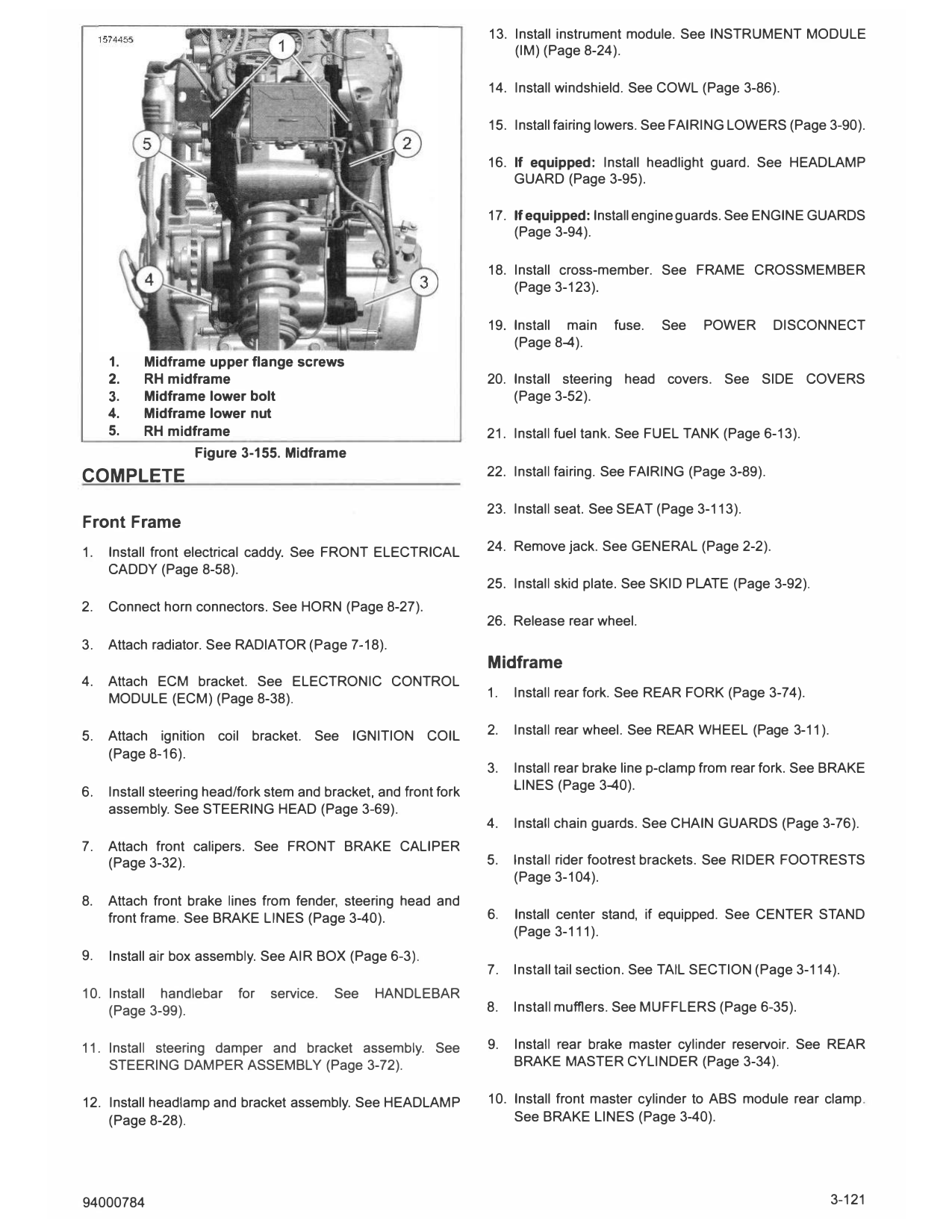
1. See Figure 3-155. Place RH and LH midframes in position.
4. Install cable strap.
2. Loosely install upper flange screws (1).
5. See Figure 3-150. Install left side cable guide.
3. Loosely install lower lower bolt and nut (3, 4).
a. Install left side cable guide (1).
4. Follow steps in Complete (Midframe), further in this section,
b. Install plastic screw (2). until upper shock bolt and rear fork are in position.
c. Install screw (3). Tighten. 5. Tighten midframe nut and bolt (3, 4).
Torque: 35-62 in-lbs (4-7 N·m) Left side cable guide Torque: 80-88 ft-lbs (108-119 N·m) Midframe lower bolt
screw and nut
6. See Figure 3-149. Install right side cable guide (1) and 6. Tighten midframe upper flange screws (1).
cable straps (2).
Torque: 125-137 ft-lbs (169-186 N·m) Midframe upper
flange screws
3-120 94000784
13. Install instrument module. See INSTRUMENT MODULE
(IM) (Page 8-24).
14. Install windshield. See COWL (Page 3-86).
15. Install fairing lowers. See FAIRING LOWERS (Page 3-90).
16. If equipped: Install headlight guard. See HEADLAMP
GUARD (Page 3-95).
17. If equipped: Install engine guards. See ENGINE GUARDS
(Page 3-94).
18. Install cross-member. See FRAME CROSSMEMBER
(Page 3-123).
19. Install main fuse. See POWER DISCONNECT
(Page 8-4).
1. Midframe upper flange screws
2. RH midframe 20. Install steering head covers. See SIDE COVERS
3. Midframe lower bolt (Page 3-52).
4. Midframe lower nut
5. RH midframe 21. Install fuel tank. See FUEL TANK (Page 6-13).
Figure 3-155. Midframe
COMPLETE 22. Install fairing. See FAIRING (Page 3-89).
23. Install seat. See SEAT (Page 3-113).
Front Frame
1. Install front electrical caddy. See FRONT ELECTRICAL 24. Remove jack. See GENERAL (Page 2-2).
CADDY (Page 8-58).
25. Install skid plate. See SKID PLATE (Page 3-92).
2. Connect horn connectors. See HORN (Page 8-27).
26. Release rear wheel.
3. Attach radiator. See RADIATOR (Page 7-18).
Midframe
4. Attach ECM bracket. See ELECTRONIC CONTROL
MODULE (ECM) (Page 8-38). 1. Install rear fork. See REAR FORK (Page 3-74).
5. Attach ignition coil bracket. See IGNITION COIL 2. Install rear wheel. See REAR WHEEL (Page 3-11 ).
(Page 8-16).
3. Install rear brake line p-clamp from rear fork. See BRAKE
6. Install steering head/fork stem and bracket, and front fork LINES (Page 3-40).
assembly. See STEERING HEAD (Page 3-69).
4. Install chain guards. See CHAIN GUARDS (Page 3-76).
7. Attach front calipers. See FRONT BRAKE CALIPER
(Page 3-32). 5. Install rider footrest brackets. See RIDER FOOTRESTS
(Page 3-104).
8. Attach front brake lines from fender, steering head and
front frame. See BRAKE LINES (Page 3-40). 6. Install center stand, if equipped. See CENTER STAND
(Page 3-111).
9. Install air box assembly. See AIR BOX (Page 6-3).
7. Install tail section. See TAIL SECTION (Page 3-114).
10. Install handlebar for service. See HANDLEBAR
(Page 3-99). 8. Install mufflers. See MUFFLERS (Page 6-35).
11. Install steering damper and bracket assembly. See 9. Install rear brake master cylinder reservoir. See REAR
STEERING DAMPER ASSEMBLY (Page 3-72). BRAKE MASTER CYLINDER (Page 3-34).
12. Install headlamp and bracket assembly. See HEADLAMP 10. Install front master cylinder to ABS module rear clamp.
(Page 8-28). See BRAKE LINES (Page 3-40).
94000784 3-121
11. Install ABS module. See ABS MODULE (Page 3-46). 13. Install under seat caddy. See UNDER SEAT CADDY
(Page 8-61 ).
a. Remove ABS module frame cover.
14. Install seat. See SEAT (Page 3-113).
b. Detach ABS module.
15. Install main fuse. See POWER DISCONNECT
12. Install crossmember. See FRAME CROSSMEMBER (Page 8-4).
(Page 3-123).
16. Install middle side and right side steering head cover. See
SIDE COVERS (Page 3-52).
3-122 94000784