3.42 Rider Footrests
Fragment manuala — str. 182–184
📋 Tekst do skopiowania (OCR/wyszukiwanie)
RIDER FOOTRESTS 3.42
PREPARE c. Install screw (4). Tighten.
Torque: 159-177 in-lbs (18-20 N·m) Footpad insert
If removing right side footrest bracket or brake pedal. screw
1. Remove main fuse. See POWER DISCONNECT
(Page 8-4).
2. Detach rear brake master cylinder from bracket. See REAR
BRAKE MASTER CYLINDER (Page 3-34).
3. Remove center stand (if equipped). See CENTER STAND
(Page 3-111).
If removing left side footrest bracket or shift lever.
1. Remove main fuse. See POWER DISCONNECT
(Page 8-4).
2. Remove center stand (if equipped). See CENTER STAND
(Page 3-111).
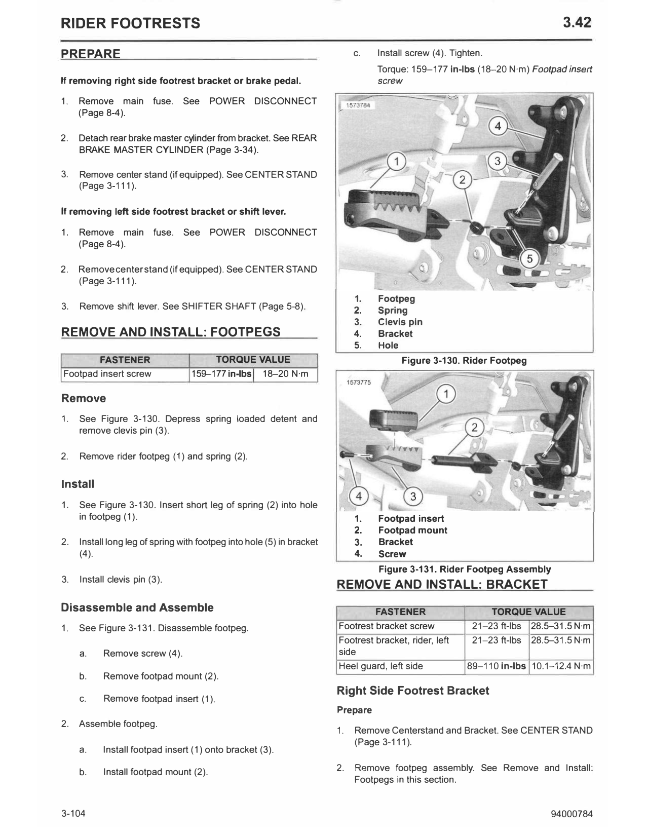
1. Footpeg
3. Remove shift lever. See SHIFTER SHAFT (Page 5-8). 2. Spring
3. Clevis pin
REMOVE AND INSTALL: FOOTPEGS 4. Bracket
5. Hole
FASTENER TORQUE VALUE Figure 3-130. Rider Footpeg
Footpad insert screw 159--177in-lbs 18-20 N·m
Remove
1. See Figure 3-130. Depress spring loaded detent and
remove clevis pin (3).
2. Remove rider footpeg (1) and spring (2).
Install
1. See Figure 3-130. Insert short leg of spring (2) into hole
in footpeg (1). 1. Footpad insert
2. Footpad mount
2. Install long leg of spring with footpeg into hole (5) in bracket 3. Bracket
(4). 4. Screw
Figure 3-131. Rider Footpeg Assembly
3. Install clevis pin (3).
REMOVE AND INSTALL: BRACKET
Disassemble and Assemble FASTENER TORQUE VALUE
1. See Figure 3-131. Disassemble footpeg. Footrest bracket screw 21-23 ft-lbs 28.5--31.5 N·m
Footrest bracket, rider, left 21-23 ft-lbs 28.5--31.5 N·m
a. Remove screw (4). side
Heel guard, left side 89-110 in-lbs 10.1-12.4 N·m
b. Remove footpad mount (2).
Right Side Footrest Bracket
c. Remove footpad insert (1).
Prepare
2. Assemble footpeg.
1. Remove Centerstand and Bracket. See CENTER STAND
(Page 3-111).
a. Install footpad insert (1) onto bracket (3).
b. Install footpad mount (2). 2. Remove footpeg assembly. See Remove and Install:
Footpegs in this section.
3-104 94000784
3. Remove brake pedal. See REAR BRAKE MASTER 2. Install screws (7). Tighten.
CYLINDER (Page 3-34).
Torque: 21-23 ft-lbs (28.5-31.5 N·m) Footrest bracket,
rider, left side
4. Remove heelguard/rear master cylinder mounting screws.
See REAR BRAKE MASTER CYLINDER (Page 3-34). 3. Install mounting screws (1) and heel guard (2). Tighten.
Torque: 89-110 in-lbs (10.1-12.4 N·m) Heel guard, left
Remove side
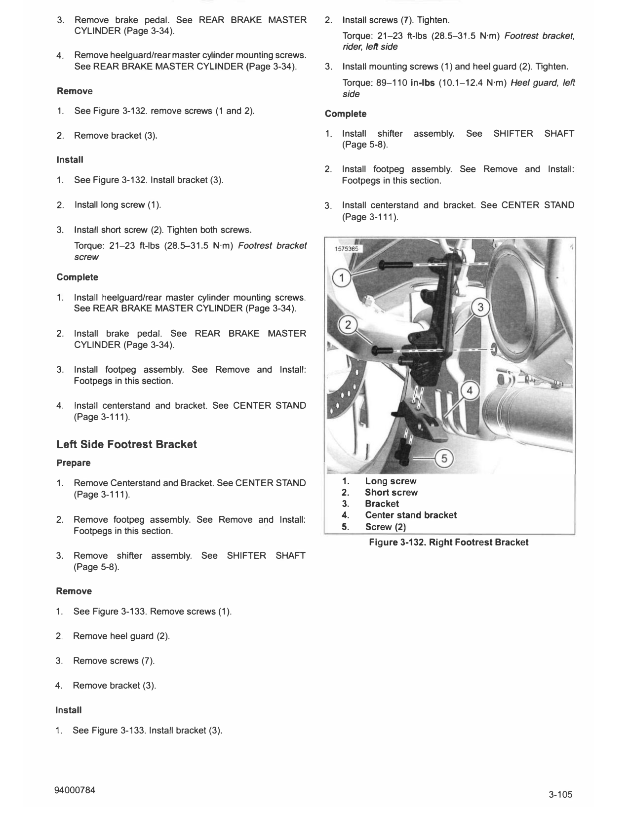
1. See Figure 3-132. remove screws (1 and 2). Complete
2. Remove bracket (3). 1. Install shifter assembly. See SHIFTER SHAFT
(Page 5-8).
Install
2. Install footpeg assembly. See Remove and Install:
1. See Figure 3-132. Install bracket (3). Footpegs in this section.
2. Install long screw (1). 3. Install centerstand and bracket. See CENTER STAND
(Page 3-111).
3. Install short screw (2). T ighten both screws.
Torque: 21-23 ft-lbs (28.5-31.5 N·m) Footrest bracket
screw
Complete
1. Install heelguard/rear master cy linder mounting screws.
See REAR BRAKE MASTER CYLINDER (Page 3-34).
2. Install brake pedal. See REAR BRAKE MASTER
CYLINDER (Page 3-34).
3. Install footpeg assembly. See Remove and Install:
Footpegs in this section.
4. Install centerstand and bracket. See CENTER STAND
(Page 3-111).
Left Side Footrest Bracket
Prepare
1. Remove C enterstand and Bracket. See CENTER STAND 1. Long screw
(Page 3-111). 2. Short screw
3. Bracket
2. Remove footpeg assembly. See Remove and Install: 4. Center stand bracket
Footpegs in this section. 5. Screw (2)
Figure 3-132. Right Footrest Bracket
3. Remove shifter assembly. See SHIFTER SHAFT
(Page 5-8).
Remove
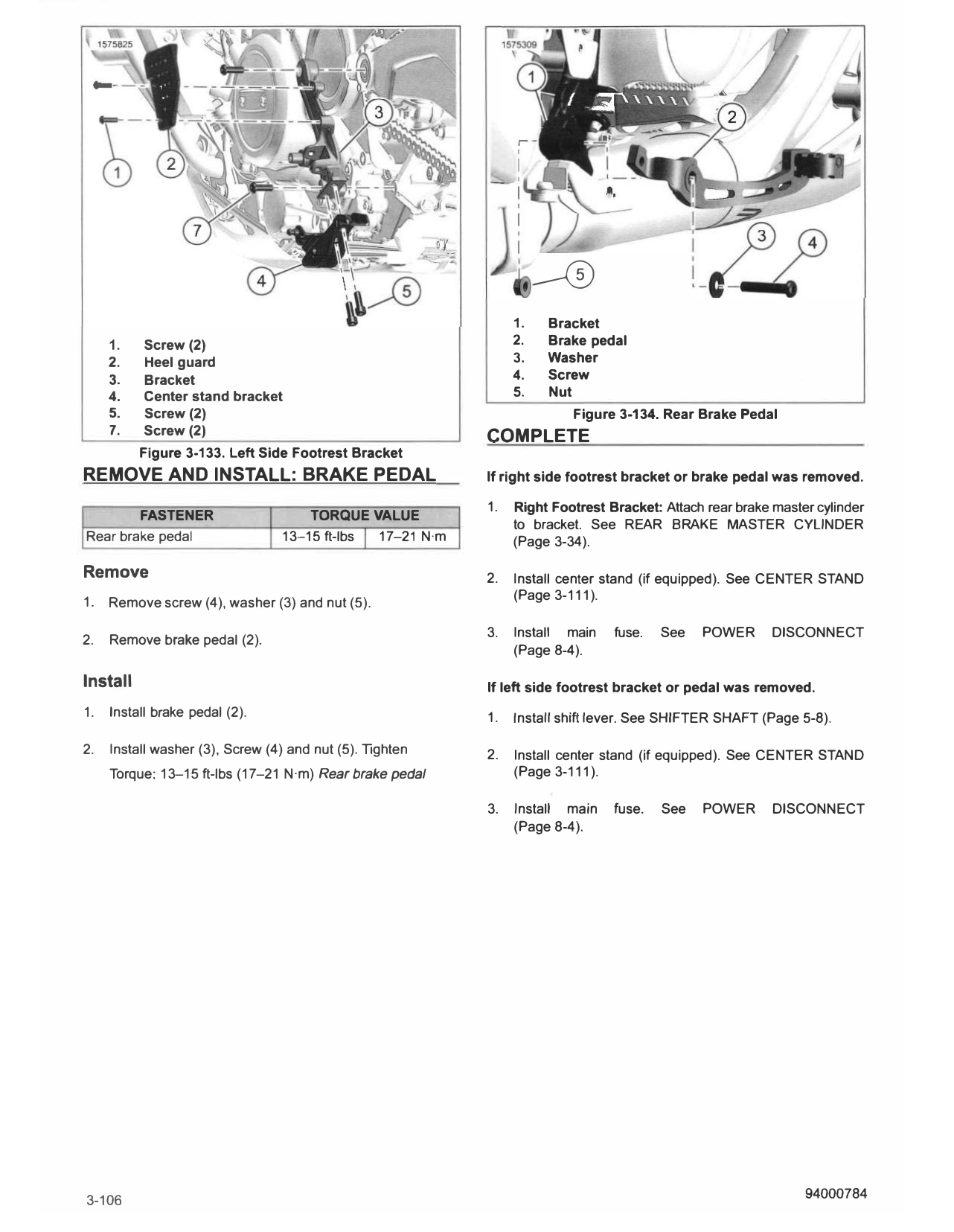
1. See Figure 3-133. Remove screws (1).
2. Remove heel guard (2).
3. Remove screws (7).
4. Remove bracket (3).
Install
1. See Figure 3-133. Install bracket (3).
I
I
I
I
I
I
I
I
---®
1. Bracket
1. Screw (2) 2. Brake pedal
2. Heel guard 3. Washer
3. Bracket 4. Screw
4. Center stand bracket 5. Nut
5. Screw (2) Figure 3-134. Rear Brake Pedal
7. Screw (2) COMPLETE
Figure 3-133. Left Side Footrest Bracket
REMOVE AND INSTALL: BR AKE PEDAL If right side footrest bracket or brake pedal was removed.
1. Right Footrest Bracket: Attach rear brake master cylinder
FASTENER TORQUE VALUE
to bracket. See REAR BRAKE MASTER CYLINDER
Rear brake pedal 13-15 ft-lbs 17-21 N·m (Page 3-34).
Remove 2. Install center stand (if equipped). See CENTER STAND
1. (Page 3-111).
Remove screw (4), washer (3) and nut (5).
3. Install main fuse. See POWER DISCONNECT
2. Remove brake pedal (2).
(Page 8-4).
Install If left side footrest bracket or pedal was removed.
1. Install brake pedal (2). 1. Install shift lever. See SHIFTER SHAFT (Page 5-8).
2. Install washer (3), Screw (4) and nut (5). Tighten 2. Install center stand (if equipped). See CENTER STAND
Torque: 13-15 ft-lbs (17-21 N·m) Rear brake pedal (Page 3-111 ).
3. Install main fuse. See POWER DISCONNECT
(Page 8-4).
3-106 94000784