3.37 Hand Grips
Fragment manuala — str. 175–176
📋 Tekst do skopiowania (OCR/wyszukiwanie)
HAND GRIPS 3.37
PREPARE b. Tighten clamp screw (4).
Torque: 22-27 in-lbs (2.5--3.1 N·m) Hand grip clamp,
1. If equipped: Remove wind deflector. See HANDLEBAR left
WIND DEFLECTORS (Page 3-96).
2. Install end cap (1). Tighten.
REMOVE Torque: 124-177 in-lbs (14-20 N·m) Handlebar end cap,
left
NOTE 3. If equipped: Connect heated grip.
When replacing heated grip, discard anchored cable strap.
a. Connect heat connector (3).
Left
b. See Figure 3-122. Place front cover (3) in position.
1. If equipped: Disconnect heated grip.
c. Tighten screws (2).
a. See Figure 3-122. Remove screws (2). Torque: 5--8 in-lbs (0.6-0.9 N·m) LHCM cover
screws, front
b. Remove front cover (3).
Right
c. See Figure 3-121. Disconnect heat connector (3).
1. See Figure 3-123. Install hand grip.
2. Remove end cap (1).
a. Align TGS tabs (2) with gaps in grip (1).
3. Remove hand grip.
b. Place grip in position.
a. Loosen clamp screw (4).
2. See Figure 3-122. Install end cap (1). Tighten.
b. Remove hand grip (2). Torque: 124-177 in-lbs (14-20 N·m) Handlebar end cap,
right
Right
3. If equipped: Connect heat connector (4).
NOTE
When replacing heated grip, discard anchored cable strap. 4. Place front cover (3) in position.
1. If equipped: Disconnect heated grip. 5. Tighten screws (2).
Torque: 5--8 in-lbs (0.6-0.9 N·m) RHCM cover screws,
a. See Figure 3-122. Remove screws (2). front
b. Remove front cover (3). 6. If equipped: Install new cable strap around heated grip
wire at white paint mark.
c. Disconnect heat connector (4).
2. Remove end cap (1).
3. See Figure 3-123. Remove grip (1).
INSTALL
FASTENER TORQUE VALUE
Hand grip clamp, left 22-27 in-lbs 2.5-3.1 N·m
Handlebar end cap, left 124-177 in-lbs 14-20 N·m
Handlebar end cap, right 124-177 in-lbs 14-20 N·m
LHCM cover screws, front 5-8 in-lbs 0.6-0.9 N·m
RHCM cover screws, front 5-8 in-lbs 0.6-0.9 N·m
Left
1. See Figure 3-121. Install hand grip.
a. Place grip (2) in position.
1461844 1461925
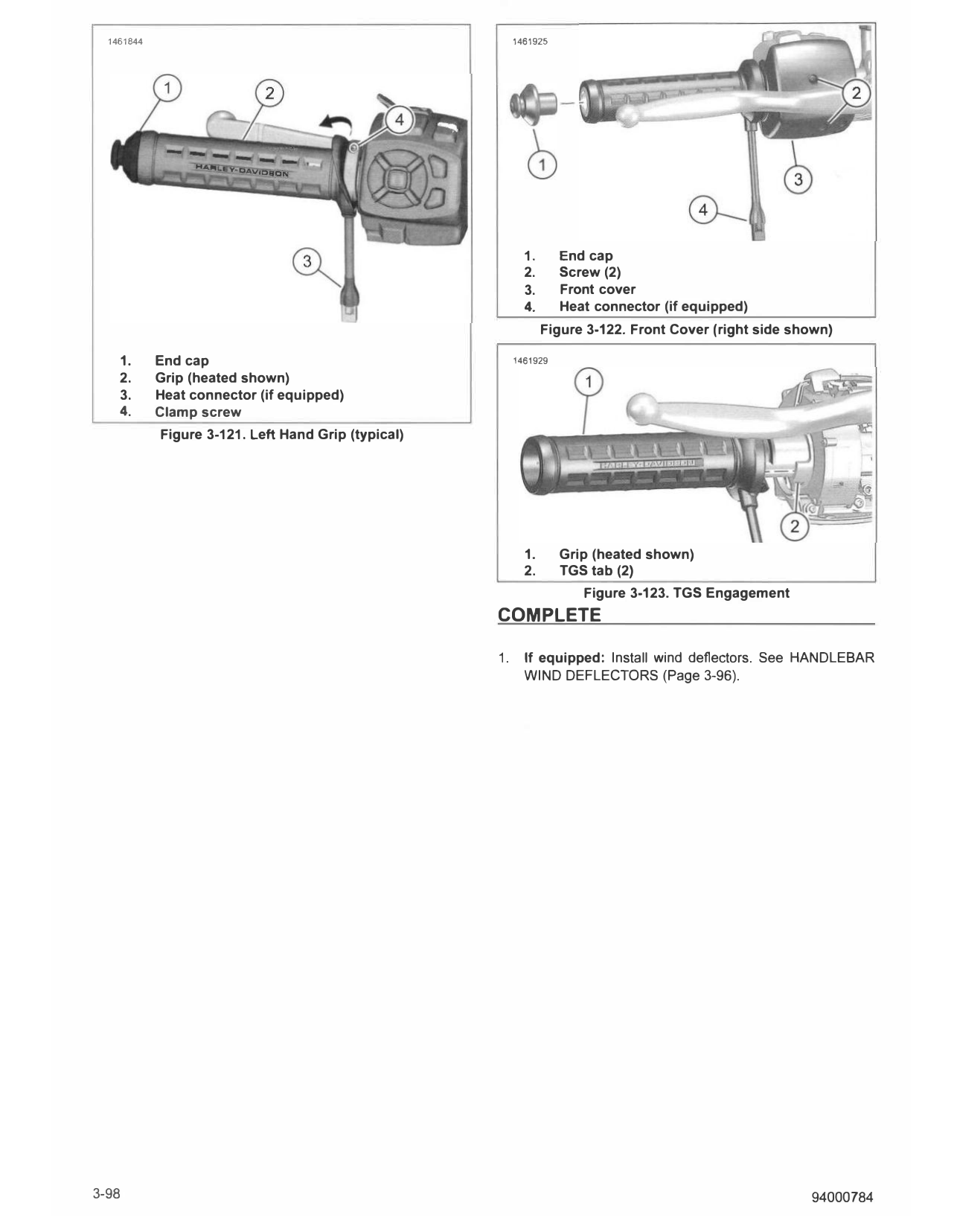
1. End cap
2. Screw (2)
3. Front cover
4. Heat connector (if equipped)
Figure 3-122. Front Cover (right side shown)
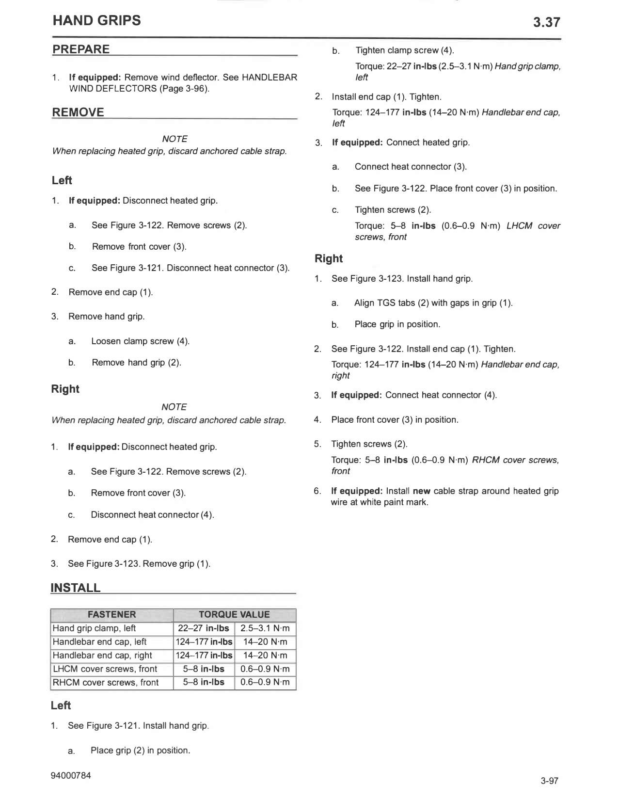
1. End cap 1461929
2. Grip (heated shown)
3. Heat connector (if equipped)
4. Clamp screw
Figure 3-121. Left Hand Grip (typical)
1. Grip (heated shown)
2. TGS tab (2)
Figure 3-123. TGS Engagement
COMPLETE
1. If equipped: Install wind deflectors. See HANDLEBAR
WIND DEFLECTORS (Page 3-96).
3-98 94000784