3.32 Fairing Lowers
Fragment manuala — str. 168–169
📋 Tekst do skopiowania (OCR/wyszukiwanie)
FAIRING LOWERS 3.32
PREPARE
NOTE
This procedure describes removal, disassembly, assembly and
installation of the right fairing lower. Left fairing lower procedure
is similar.
1. Position motorcycle upright. See Secure the Motorcycle
for Service (Page 2-2).
2. Remove main fuse. See POWER DISCONNECT
(Page 8-4).
3. Remove right engine guard. See ENGINE GUARDS
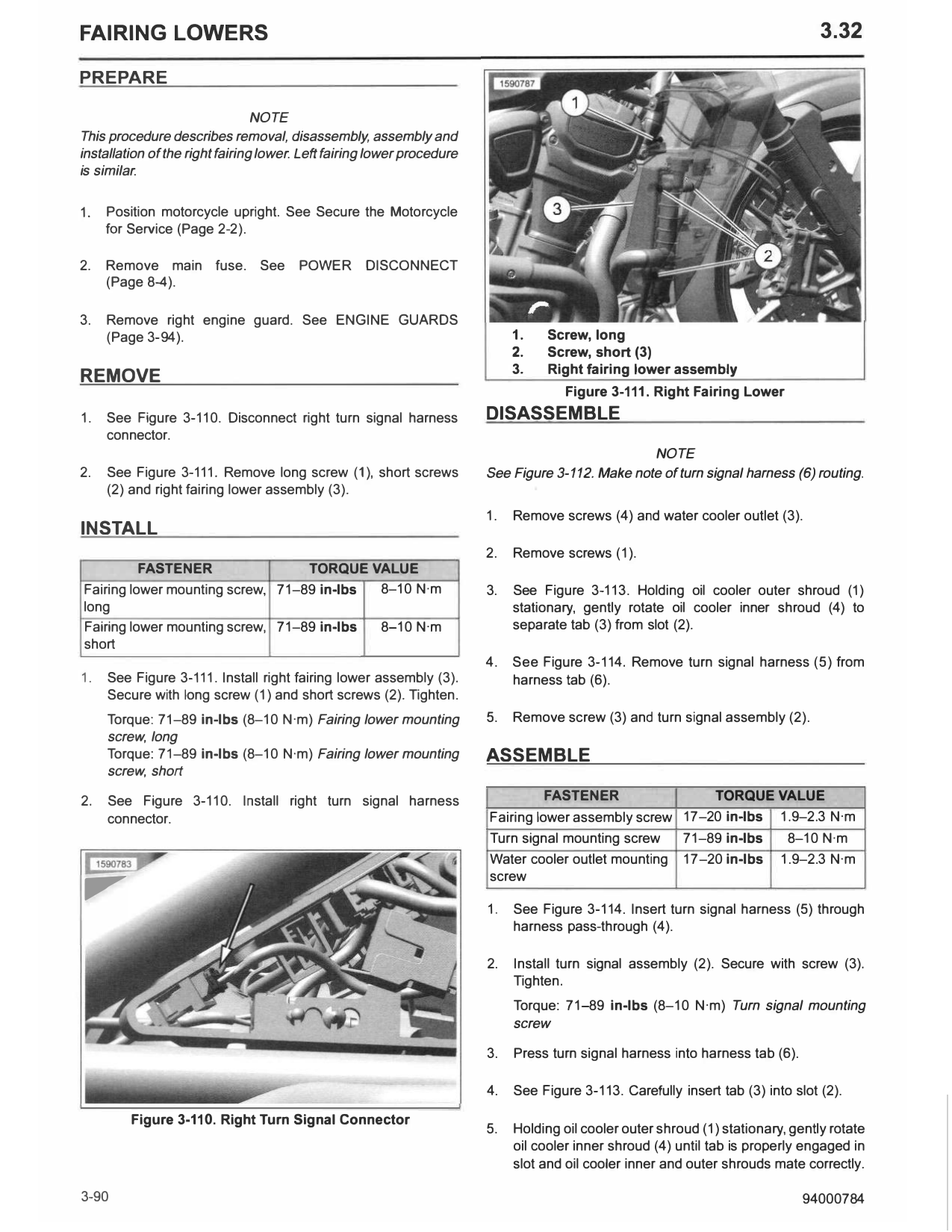
(Page 3-94). 1. Screw, long
2. Screw, short (3)
3. Right fairing lower assembly
REMOVE
Figure 3-111. Right Fairing Lower
1. See Figure 3-110. Disconnect right turn signal harness DISASSEMBLE
connector.
NOTE
2. See Figure 3-111. Remove long screw (1), short screws See Figure 3-112. Make note of turn signal harness (6) routing.
(2) and right fairing lower assembly (3).
1. Remove screws (4) and water cooler outlet (3).
INSTALL
2. Remove screws (1).
FASTENER TORQUE VALUE
Fairing lower mounting screw, 71-89 in-lbs 8-10 N·m 3. See Figure 3-113. Holding oil cooler outer shroud (1)
long stationary, gently rotate oil cooler inner shroud (4) to
Fairing lower mounting screw, 71-89 in-lbs 8-10 N·m separate tab (3) from slot (2).
short
4. See Figure 3-114. Remove turn signal harness (5) from
1. See Figure 3-111. Install right fairing lower assembly (3). harness tab (6).
Secure with long screw (1) and short screws (2). Tighten.
Torque: 71-89 in-lbs (8-10 N·m) Fairing lower mounting 5. Remove screw (3) and turn signal assembly (2).
screw, long
Torque: 71-89 in-lbs (8-10 N·m) Fairing lower mounting ASSEMBLE
screw, short
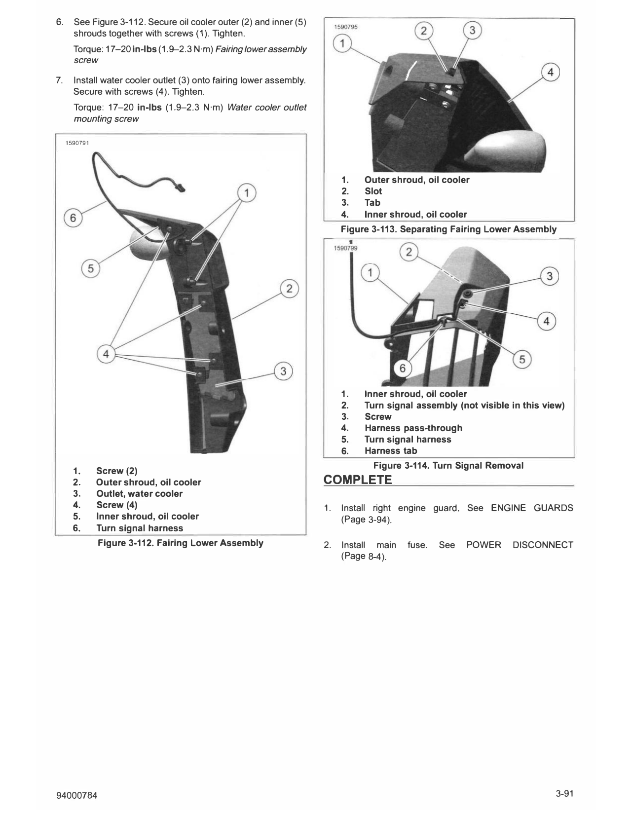
2. See Figure 3-110. Install right turn signal harness FASTENER TORQUE VALUE
connector. Fairing lower assembly screw 17-20 in-lbs 1.9-2.3 N·m
,,,,
Turn signal mounting screw 71-89 in-lbs 8-10 N·m
Water cooler outlet mounting 17-20 in-lbs 1.9-2.3 N·m
screw
1. See Figure 3-114. Insert turn signal harness (5) through
harness pass-through (4).
2. Install turn signal assembly (2). Secure with screw (3).
Tighten.
Torque: 71-89 in-lbs (8-10 N·m) Turn signal mounting
screw
3. Press turn signal harness into harness tab (6).
4. See Figure 3-113. Carefully insert tab (3) into slot (2).
Figure 3-110. Right Turn Signal Connector
5. Holding oil cooler outer shroud (1) stationary, gently rotate
oil cooler inner shroud (4) until tab is properly engaged in
slot and oil cooler inner and outer shrouds mate correctly.
3-90 94000784
6. See Figure 3-112. Secure oil cooler outer (2) and inner (5)
shrouds together with screws (1 ). Tighten.
Torque: 17-20 in-lbs (1.9-2.3 N·m) Fairing lower assembly
screw
7. Install water cooler outlet (3) onto fairing lower assembly.
Secure with screws (4). Tighten.
Torque: 17-20 in-lbs (1.9-2.3 N·m) Water cooler outlet
mounting screw
1590791
1. Outer shroud, oil cooler
2. Slot
3. Tab
4. Inner shroud, oil cooler
Figure 3-113. Separating Fairing Lower Assembly
1. Inner shroud, oil cooler
2. Turn signal assembly (not visible in this view)
3. Screw
4. Harness pass-through
5. Turn signal harness
6. Harness tab
Figure 3-114. Turn Signal Removal
1. Screw (2)
2. Outer shroud, oil cooler COMPLETE
3. Outlet, water cooler
4. Screw (4) 1. Install right engine guard. See ENGINE GUARDS
5. Inner shroud, oil cooler (Page 3-94).
6. Turn signal harness
Figure 3-112. Fairing Lower Assembly 2. Install main fuse. See POWER DISCONNECT
(Page 8-4).
94000784 3-91