3.29 Clutch Control
Fragment manuala — str. 160–163
📋 Tekst do skopiowania (OCR/wyszukiwanie)
CLUTCH CONTROL 3.29
PREPARE 2. See Figure 3-96. Remove clutch hand control assembly.
1. Remove right side steering head cover. See SIDE a. Disconnect clutch cable upper end.
COVERS (Page 3-52).
b. Note position of clutch hand control assembly (3).
2. Remove main fuse. See POWER DISCONNECT c. Remove screws (2).
(Page 8-4).
d. Remove clamp (1).
3. Remove left handlebar wind deflector. See HANDLEBAR
WIND DEFLECTORS (Page 3-96).
Clutch Switch
4. Loosen clutch cable. See CHECK AND ADJUST CLUTCH 1. Remove Clutch switch. See CLUTCH SWITCH
(Page 2-18). (Page 8-21).
5. RA1250S Models: Remove upper shock bolt for clearance. Complete Cable
See REAR SHOCK ABSORBER (Page 3-78).
1. See Figure 3-98. thru See Figure 3-100. Remove clutch
REMOVE cable from vehicle
a. Discard cable straps (1 ).
Clutch Cable: Lower End
b. Remove clutch cable.
1. See Figure 3-97. Loosen clutch cable.
CLEAN AND INSPECT
a. Slide boot (1) away from cable housing end (2).
b. Loosen jamnut (4). 1. Inspect clutch lever and cable for wear or damage. Replace
or repair as necessary.
c. Turn adjuster (3) to loosen cable housing.
2. Inspect clutch cable. Replace as necessary.
d. Loosen mid-cable adjuster to maximum free play.
NOTICE
2. See Figure 3-101. Disconnect from clutch actuator.
The clutch control cable must be oiled and adjusted
a. Remove clutch cable (2) end from cable joint (1). periodically to compensate for lining wear. Failure to oil
and adjust the clutch control cable can result in equipment
b. Remove clutch cable from clutch cable boss (3). damage. (00203c)
Clutch Cable: Upper End 3. Lubricate clutch cable and hand lever pivot pin hole with
HARLEY LUBE.
1. See Figure 3-97. Remove clutch cable.
INSTALL
a. Slide boot (1) away from cable housing end (2).
b. Remove clutch switch cover. FASTENER TORQUE VALUE
Clutch hand control bracket 60-80 in-lbs 6.8-9 N·m
I
c. Loosen jamnut (4). screw
d. Turn adjuster (3) to loosen cable housing. See . Clutch Switch
e. Align adjuster (3) and adjuster lock (4) to allow cable 1. Install clutch switch. See CLUTCH SWITCH (Page 8-21).
(5) removal.
f. Remove cable end (6) from slot (7).
Clutch Hand Control
1. See Figure 3-96. Install clutch hand control assembly.
Clutch Hand Control
a. Install clutch hand control assembly (3) on handlebar.
1. Disconnect clutch switch connector. See CLUTCH
SWITCH (Page 8-21). b. Install clamp (2).
3-82 94000784
c. Install screws (1).
Torque: 60-80 in-lbs (6.8-9 N·m) Clutch hand
control bracket screw
d. Install clutch cable upper end.
e. Connect clutch switch connector and cover. See
CLUTCH SWITCH (Page 8-21).
Clutch Cable: Lower End
1. See Figure 3-101. Install clutch cable.
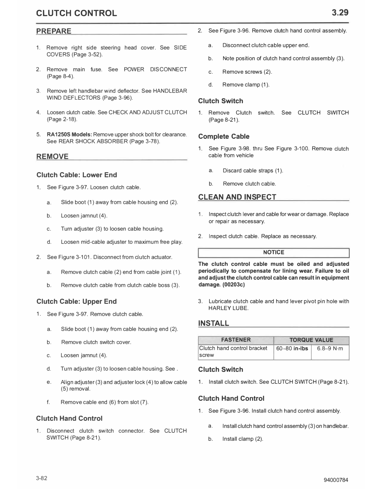
a. Route clutch cable between rear shock and midframe 1. Boot
toward clutch cable boss. 2. Cable housing end
3. Adjuster
b. Install clutch cable (2) into clutch cable boss (3). 4. Adjuster lock
5. Cable
c. Install clutch cable into cable joint (1). 6. Cable end
7. Slot
Clutch Cable: Upper End Figure 3-97. Clutch Cable at Hand Lever
1. See Figure 3-97. Install clutch cable.
a. Verify slots in clutch cable adjuster (3), adjuster lock
(4) and clutch hand lever assembly are aligned.
b. Install cable end (6) into slot (7).
c. Install clutch cable through clutch hand lever
assembly, clutch cable adjuster and adjuster lock.
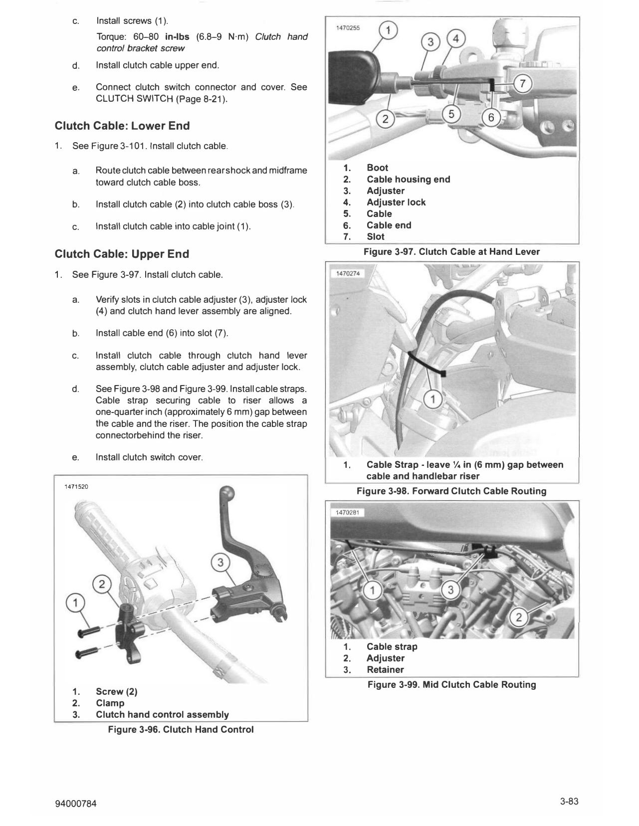
d. See Figure 3-98 and Figure 3-99. Install cable straps.
Cable strap securing cable to riser allows a
one-quarter inch (approximately 6 mm) gap between
the cable and the riser. The position the cable strap
connectorbehind the riser.
e. Install clutch switch cover.
1. Cable Strap - leave¼ in (6 mm) gap between
cable and handlebar riser
1471520
Figure 3-98. Forward Clutch Cable Routing
'
1. Cable strap
2. Adjuster
3. Retainer
Figure 3-99. Mid Clutch Cable Routing
1. Screw (2)
2. Clamp
3. Clutch hand control assembly
Figure 3-96. Clutch Hand Control
94000784 3-83
DISASSEMBLE
1. See Figure 3-102. Remove Cable adjuster (1).
2. Remove clutch lever.
a. Remove nut (4).
b. Remove lever pivot screw (3).
c. Remove clutch lever (5).
ASSEMBLE
FASTENER TORQUE VALUE
Clutch lever pivot nut 44-62 in-lbs 5-7 N·m
1. See Figure 3-102. Install clutch lever.
Figure 3-100. Rear Clutch Cable Routing
a. Install clutch lever (5) in lever mount (2).
b. Install lever pivot screw (3).
c. Install nut (4). Tighten.
Torque: 44-62 in-lbs (5-7 N·m) Clutch lever pivot
nut
2. Install cable adjuster (1) in lever mount.
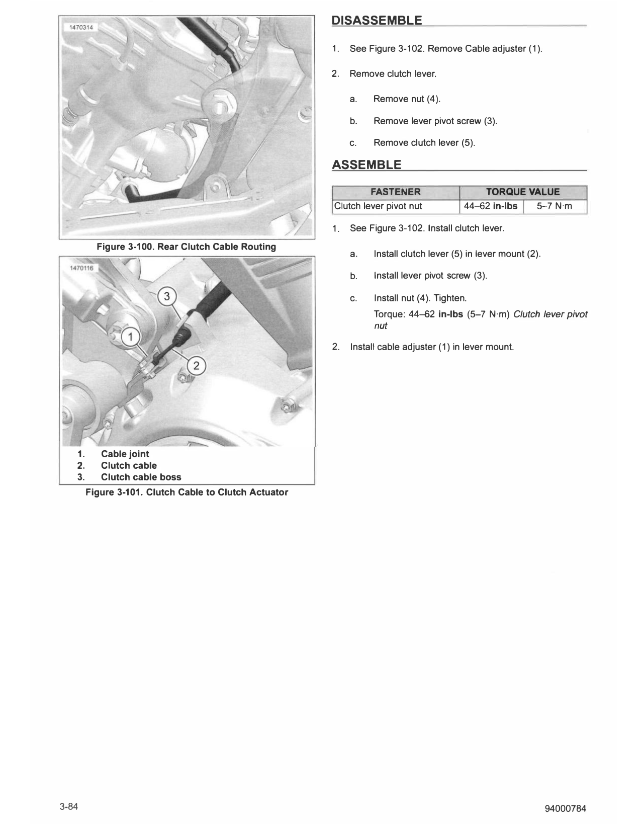
1. Cable joint
2. Clutch cable
3. Clutch cable boss
Figure 3-101. Clutch Cable to Clutch Actuator
3-84 94000784
1477646
......
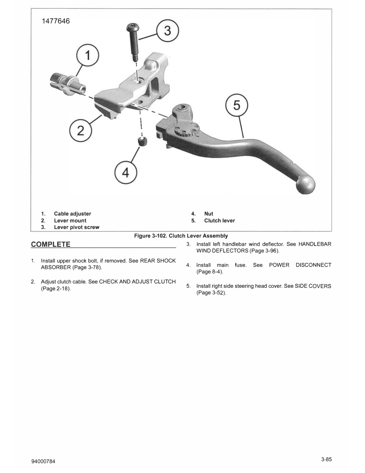
1. Cable adjuster 4. Nut
2. Lever mount 5. Clutch lever
3. Lever pivot screw
Figure 3-102. Clutch Lever Assembly
COMPLETE 3. Install left handlebar wind deflector. See HANDLEBAR
WIND DEFLECTORS (Page 3-96).
1. Install upper shock bolt, if removed. See REAR SHOCK
ABSORBER (Page 3-78). 4. Install main fuse. See POWER DISCONNECT
(Page 8-4).
2. Adjust clutch cable. See CHECK AND ADJUST CLUTCH
(Page 2-18). 5. Install right side steering head cover. See SIDE COVERS
(Page 3-52).
94000784 3-85