🏍️ PAN AMERICA SERWIS

3.28 Rear Shock Absorber

Fragment manuala — str. 156–159

📋 Tekst do skopiowania (OCR/wyszukiwanie)
REAR SHOCK ABSORBER                                                                                                 3.28

PREPARE

1.     Secure motorcycle for service. See Secure the Motorcycle
       for Service (Page 2-2).

2.     Remove seat. See SEAT (Page 3-113).

3.     Remove the main fuse. See POWER DISCONNECT
       (Page 8-4).

4.     Remove rear fork. See REAR FORK (Page 3-74).
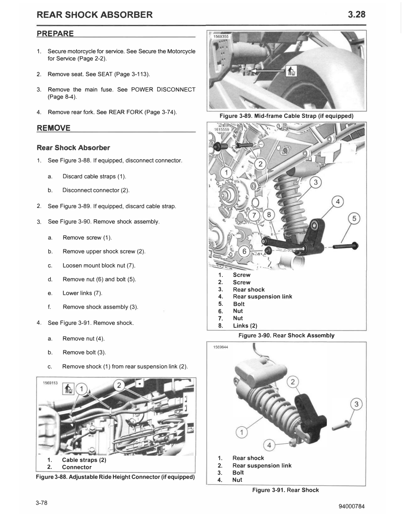
                                                                      Figure 3-89. Mid-frame Cable Strap (if equipped)

REMOVE

Rear Shock Absorber
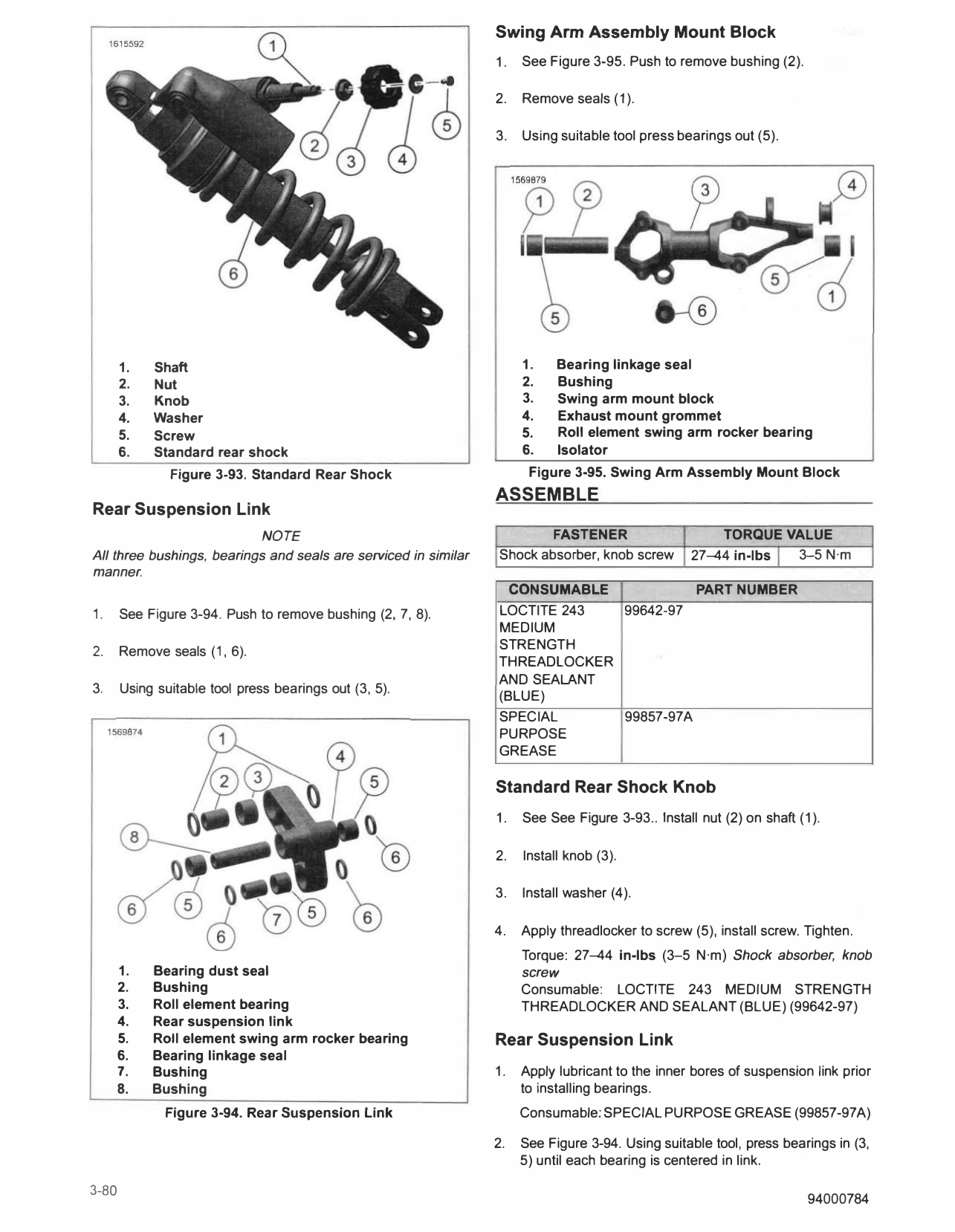
1.     See Figure 3-88. If equipped, disconnect connector.

       a.   Discard cable straps (1).

       b.   Disconnect connector (2).

2.     See Figure 3-89. If equipped, discard cable strap.

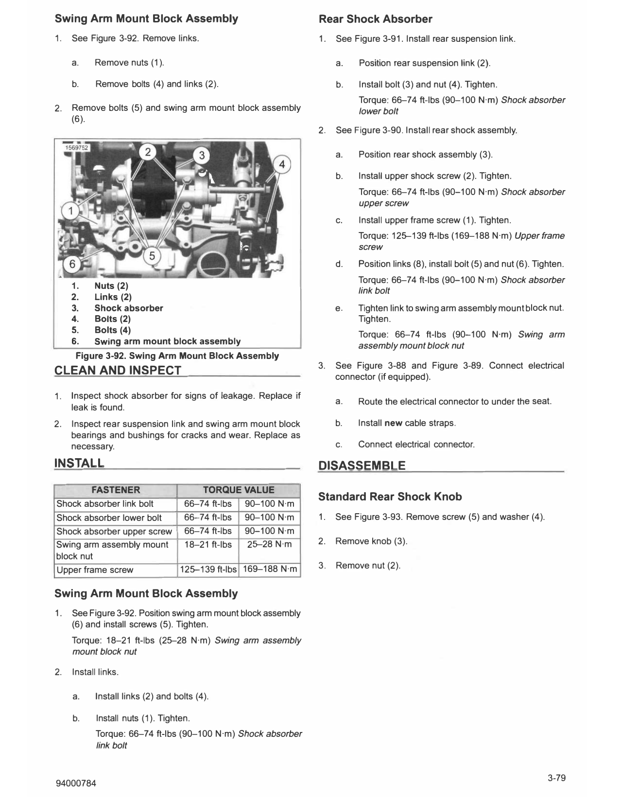
3.     See Figure 3-90. Remove shock assembly.

       a.   Remove screw (1 ).

       b.   Remove upper shock screw (2).                                               :..a._'-J•
                                                                              ./,,..          -·1..
       C.   Loosen mount block nut (7).                           ·��--          ,;,--L-
                                                                    1.  Screw
       d.   Remove nut (6) and bolt (5).                            2.  Screw
                                                                    3.  Rear shock
       e.   Lower links (7).
                                                                    4.  Rear suspension link
                                                                    5.  Bolt
       f.   Remove shock assembly (3).
                                                                    6.  Nut
                                                                    7.  Nut
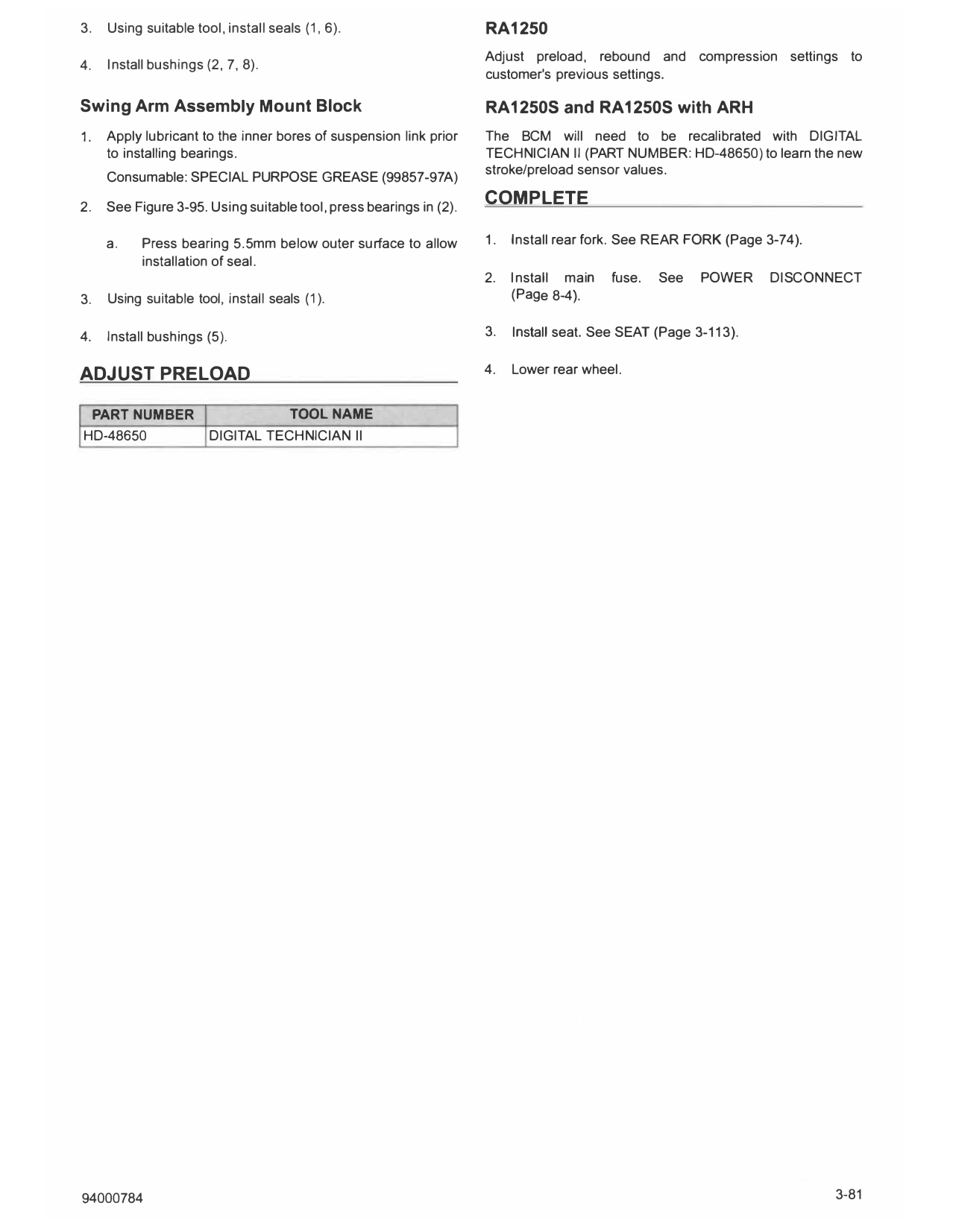
4.     See Figure 3-91. Remove shock.
                                                                    8.  Links (2)
                                                                               Figure 3-90. Rear Shock Assembly
       a.   Remove nut (4).
                                                                   1569844
       b.   Remove bolt (3).

       c.   Remove shock (1) from rear suspension link (2).

     1.     Cable straps (2)                                        1.       Rear shock
     2.     Connector                                               2.       Rear suspension link
                                                                    3.       Bolt
Figure 3-88. Adjustable Ride Height Connector (if equipped)
                                                                    4.       Nut
                                                                                       Figure 3-91. Rear Shock

Swing Arm Mount Block Assembly                                  Rear Shock Absorber
1.   See Figure 3-92. Remove links.                             1.   See Figure 3-91. Install rear suspension link.

     a.    Remove nuts (1).                                          a.   Position rear suspension link (2).

     b.     Remove bolts (4) and links (2).                          b.   Install bolt (3) and nut (4). Tighten.
                                                                          Torque: 66-74 ft-lbs (90-100 N·m) Shock absorber
2.   Remove bolts (5) and swing arm mount block assembly                  lower bolt
     (6).
                                                                2.   See Figure 3-90. Install rear shock assembly.

                                                                     a.   Position rear shock assembly (3).

                                                                     b.   Install upper shock screw (2). Tighten.
                                                                          Torque: 66-74 ft-lbs (90-100 N·m) Shock absorber
                                                                          upper screw
                                                                     c.   Install upper frame screw (1). Tighten.
                                                                          Torque: 125--139 ft-lbs (169-188 N·m) Upper frame
                                                                          screw
                                                                     d.   Position links (8), install bolt (5) and nut (6). Tighten.
                                                                          Torque: 66-74 ft-lbs (90-100 N·m) Shock absorber
     1.    Nuts (2)
                                                                          link bolt
     2.    Links (2)
     3.    Shock absorber                                            e.   Tighten link to swing arm assembly mount block nut.
     4.    Bolts (2)                                                      Tighten.
     5.    Bolts (4)                                                      Torque: 66-74 ft-lbs (90-100 N·m) Swing arm
     6.    Swing arm mount block assembly                                 assembly mount block nut
      Figure 3-92. Swing Arm Mount Block Assembly
                                                                3.   See Figure 3-88 and Figure 3-89. Connect electrical
CLEAN AND INSPECT                                                    connector (if equipped).

1.   Inspect shock absorber for signs of leakage. Replace if
                                                                     a.   Route the electrical connector to under the seat.
     leak is found.
2.   Inspect rear suspension link and swing arm mount block          b.   Install new cable straps.
     bearings and bushings for cracks and wear. Replace as
     necessary.                                                      c.   Connect electrical connector.

INSTALL                                                         DISASSEMBLE
        FASTENER                         TORQUE VALUE
                                                                Standard Rear Shock Knob
Shock absorber link bolt             66-74 ft-lbs 90-100 N·m
Shock absorber lower bolt   66-74 ft-lbs 90-100 N·m             1.   See Figure 3-93. Remove screw (5) and washer (4).
Shock absorber upper screw 66-74 ft-lbs 90-100 N·m
Swing arm assembly mount    18-21 ft-lbs    25--28 N·m          2.   Remove knob (3).
block nut
Upper frame screw          125--139 ft-lbs 169-188 N·m          3.   Remove nut (2).

Swing Arm Mount Block Assembly
1.   See Figure 3-92. Position swing arm mount block assembly
     (6) and install screws (5). Tighten.
     Torque: 18-21 ft-lbs (25-28 N·m) Swing arm assembly
     mount block nut

2.   Install links.

     a.     Install links (2) and bolts (4).

     b.     Install nuts (1). Tighten.
            Torque: 66-74 ft-lbs (90-100 N·m) Shock absorber
            link bolt

                                                                 Swing Arm Assembly Mount Block
                                                                 1.   See Figure 3-95. Push to remove bushing (2).

                                                                 2.   Remove seals (1 ).

                                                                 3.   Using suitable tool press bearings out (5).

       1.   Shaft                                                     1.    Bearing linkage seal
       2.   Nut                                                       2.    Bushing
       3.   Knob                                                      3.    Swing arm mount block
       4.   Washer                                                    4.    Exhaust mount grommet
       5.   Screw                                                     5.    Roll element swing arm rocker bearing
       6.   Standard rear shock                                       6.    Isolator
               Figure 3-93. Standard Rear Shock                        Figure 3-95. Swing Arm Assembly Mount Block
                                                                 ASSEMBLE
Rear Suspension Link
                           NOTE                                          FASTENER                     TORQUE VALUE
All three bushings, bearings and seals are serviced in similar   Shock absorber, knob screw       27-44 in-lbs 3-5 N·m
manner.
                                                                   CONSUMABLE           PART NUMBER
1.     See Figure 3-94. Push to remove bushing (2, 7, 8).        LOCTITE 243  99642-97
                                                                 MEDIUM
2.     Remove seals (1, 6).                                      STRENGTH
                                                                 THREADLOCKER
                                                                 AND SEALANT
3.     Using suitable tool press bearings out (3, 5).
                                                                 (BLUE)
                                                                 SPECIAL      99857-97A
                                                                 PURPOSE
                                                                 GREASE

                                                                 Standard Rear Shock Knob
                                                                 1.   See See Figure 3-93.. Install nut (2) on shaft (1).

                                                                 2.   Install knob (3).

                                                                 3.   Install washer (4).

                                                                 4.   Apply threadlocker to screw (5), install screw. Tighten.
                                                                      Torque: 27-44 in-lbs (3-5 N·m} Shock absorber, knob
     1.     Bearing dust seal                                         screw
     2.     Bushing                                                   Consumable: LOCTITE 243 MEDIUM STRENGTH
     3.     Roll element bearing                                      THREADLOCKER AND SEALANT (BLUE) (99642-97)
     4.     Rear suspension link
     5.     Roll element swing arm rocker bearing                Rear Suspension Link
     6.     Bearing linkage seal
     7.     Bushing                                              1.   Apply lubricant to the inner bores of suspension link prior
     8.     Bushing                                                   to installing bearings.
              Figure 3-94. Rear Suspension Link                       Consumable: SPECIAL PURPOSE GREASE (99857-97A)

                                                                 2.   See Figure 3-94. Using suitable tool, press bearings in (3,
                                                                      5) until each bearing is centered in link.

3.   Using suitable tool, install seals (1, 6).                     RA1250
                                                                    Adjust preload, rebound and compression settings to
4.   Install bushings (2, 7, 8).
                                                                    customer's previous settings.

Swing Arm Assembly Mount Block                                      RA1250S and RA1250S with ARH
1.   Apply lubricant to the inner bores of suspension link prior    The BCM will need to be recalibrated with DIGITAL
     to installing bearings.                                        TECHNICIAN II (PART NU MBER: HD-48650) to learn the new
     Consumable: SPECIAL PURPOSE GREASE (99857-97A)                 stroke/preload sensor values.

2.   See Figure 3-95. Using suitable tool, press bearings in (2).
                                                                    COMPLETE

     a.    Press bearing 5.5mm below outer surface to allow         1.   Install rear fork. See REAR FORK (Page 3-74).
           installation of seal.
                                                                    2.   Install main   fuse.   See   POWER      DISCONNECT
3.   Using suitable tool, install seals (1 ).                            (Page 8-4).

4.   Install bushings (5).                                          3.   Install seat. See SEAT (Page 3-113).

ADJUST PRELOAD                                                      4.   Lower rear wheel.

 PART NUMBER                          TOOL NAME
HD-48650               DIGITAL TECHNICIAN II

94000784                                                                                                                 3-81