3.26 Rear Fork
Fragment manuala — str. 152–153
📋 Tekst do skopiowania (OCR/wyszukiwanie)
REAR FORK 3.26
PREPARE
1. Remove center stand, if equipped. See CENTER STAND
(Page 3-111).
2. Remove rider footrest brackets. See RIDER FOOTRESTS
(Page 3-104).
3. Remove mufflers. See MUFFLERS (Page 6-35).
4. Remove chain guards. See CHAIN GUARDS (Page 3-76).
5. Remove rear brake line p-clamp from rear fork. See
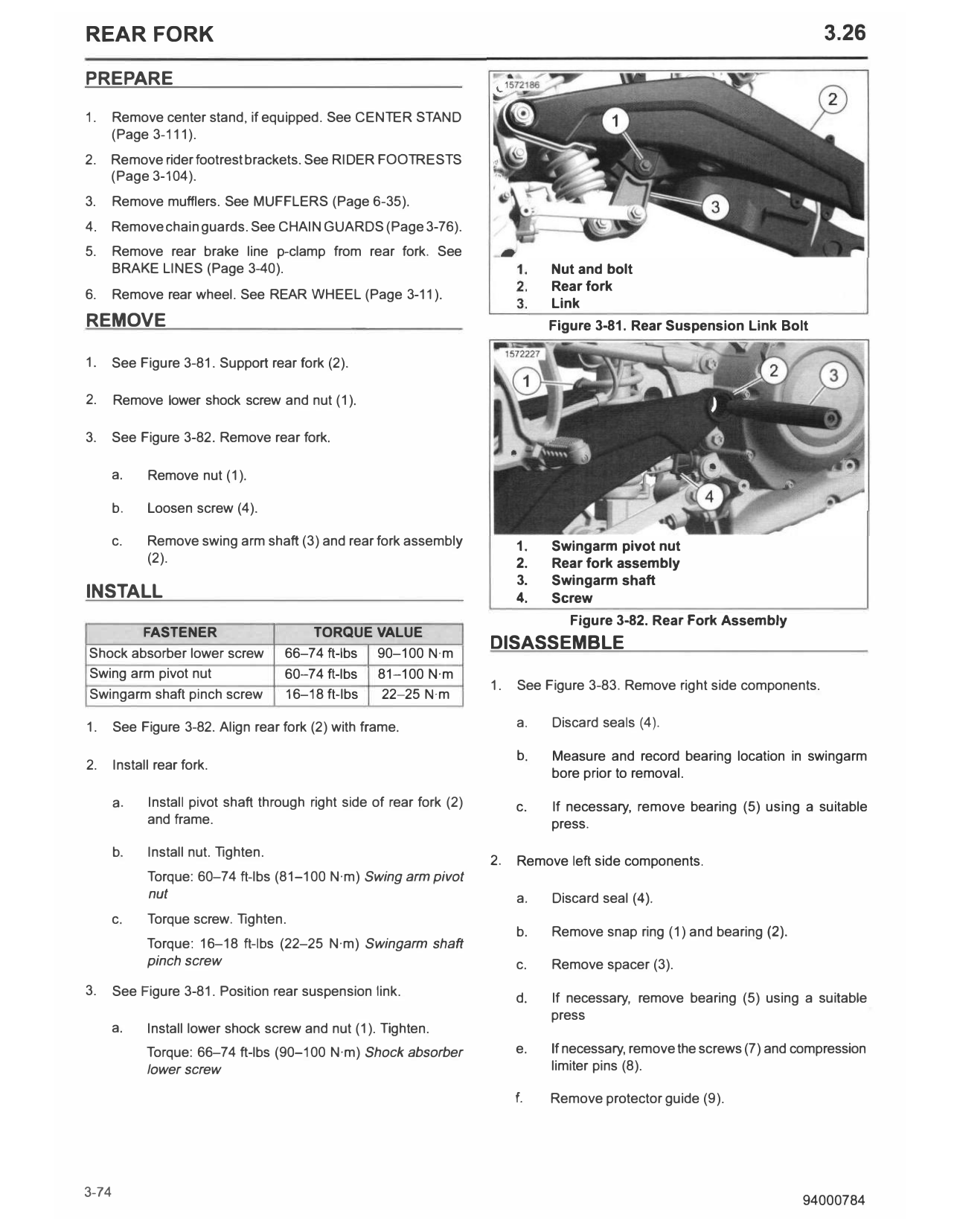
BRAKE LINES (Page 3-40). Nut and bolt
Rear fork
6. Remove rear wheel. See REAR WHEEL (Page 3-11).
Link
REMOVE Figure 3-81. Rear Suspension Link Bolt
1. See Figure 3-81. Support rear fork (2).
2. Remove lower shock screw and nut (1).
3. See Figure 3-82. Remove rear fork.
a. Remove nut (1).
b. Loosen screw (4).
c. Remove swing arm shaft (3) and rear fork assembly 1. Swingarm pivot nut
(2). 2. Rear fork assembly
3. Swingarm shaft
INSTALL 4. Screw
Figure 3-82. Rear Fork Assembly
FASTENER TORQUE VALUE
Shock absorber lower screw 66-74 ft-lbs 90-100 N·m
DISASSEMBLE
Swing arm pivot nut 60-74 ft-lbs 81-100 N·m
1. See Figure 3-83. Remove right side components.
Swingarm shaft pinch screw 16-18 ft-lbs 22-25 N·m
1. See Figure 3-82. Align rear fork (2) with frame. a. Discard seals (4).
b. Measure and record bearing location in swingarm
2. Install rear fork.
bore prior to removal.
a. Install pivot shaft through right side of rear fork (2) c. If necessary, remove bearing (5) using a suitable
and frame. press.
b. Install nut. Tighten.
2. Remove left side components.
Torque: 60-74 ft-lbs (81-100 N·m) Swing arm pivot
nut a. Discard seal (4).
c. Torque screw. Tighten.
b. Remove snap ring (1) and bearing (2).
Torque: 16-18 ft-lbs (22-25 N·m) Swingarm shaft
pinch screw c. Remove spacer (3).
3. See Figure 3-81. Position rear suspension link.
d. If necessary, remove bearing (5) using a suitable
press
a. Install lower shock screw and nut (1). Tighten.
Torque: 66-74 ft-lbs (90-100 N·m) Shock absorber e. If necessary, remove the screws (7) and compression
lower screw limiter pins (8).
f. Remove protector guide (9).
1. Apply lubricant to the inner bores of the swingarm prior to
installing bearings.
Consumable: SPECIAL PURPOSE GREASE (99857-97A)
2. See Figure 3-83. Install right side components.
a. Install bearings (5) to previously recorded depth
using a suitable press.
b. Install new seals (4).
3. See Figure 3-83. Install left side components.
a.
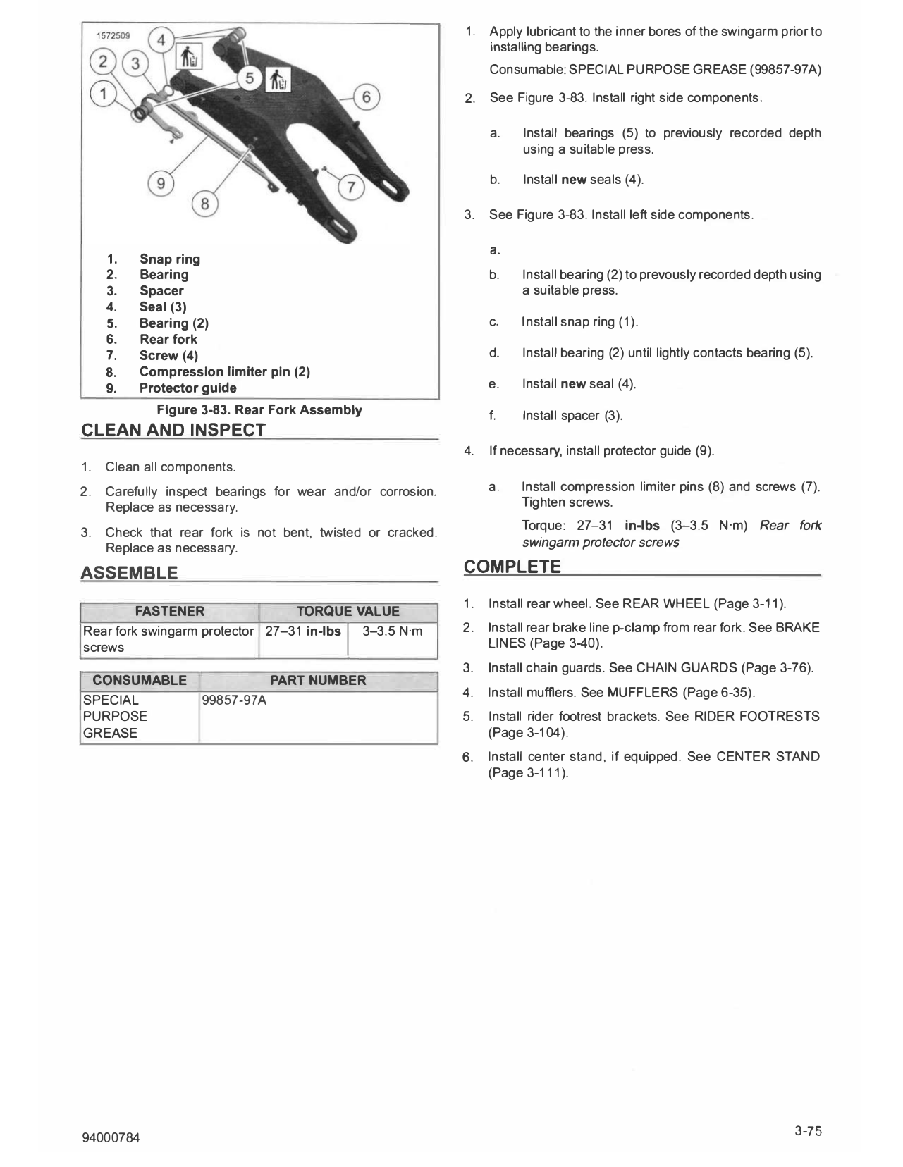
1. Snap ring
2. Bearing b. Install bearing (2) to prevously recorded depth using
3. Spacer a suitable press.
4. Seal (3)
5. Bearing (2) c. Install snap ring (1).
6. Rear fork
7. Screw (4) d. Install bearing (2) until lightly contacts bearing (5).
8. Compression limiter pin (2)
9. Protector guide e. Install new seal (4).
Figure 3-83. Rear Fork Assembly f. Install spacer (3).
CLEAN AND INSPECT
4. If necessary, install protector guide (9).
1. Clean all components.
2. Carefully inspect bearings for wear and/or corrosion. a. Install compression limiter pins (8) and screws (7).
Replace as necessary. Tighten screws.
3. Check that rear fork is not bent, twisted or cracked. Torque: 27-31 in-lbs (3-3.5 N·m) Rear fork
Replace as necessary. swingarm protector screws
ASSEMBLE COMPLETE
1. Install rear wheel. See REAR WHEEL (Page 3-11).
FASTENER TORQUE VALUE
Rear fork swingarm protector 27-31 in-lbs 3-3.5 N·m 2. Install rear brake line p-clamp from rear fork. See BRAKE
I LINES (Page 3-40).
screws
3. Install chain guards. See CHAIN GUARDS (Page 3-76).
CONSUMABLE PART NUMBER
4. Install mufflers. See MUFFLERS (Page 6-35).
SPECIAL 99857-97A
PURPOSE 5. Install rider footrest brackets. See RIDER FOOTRESTS
GREASE (Page 3-104).
6. Install center stand, if equipped. See CENTER STAND
(Page 3-111).