🏍️ PAN AMERICA SERWIS

3.22 Front Fork

Fragment manuala — str. 131–146

📋 Tekst do skopiowania (OCR/wyszukiwanie)
FRONT FORK                                                                                                                             3.22
CHECK FOR OIL LEAK                                                  Check Oil Leak
                                                                    1.        Observe oil ring.
Fork Oil Seals
                                                                    2.        Wipe fork clean.
The fork oil seal allows a fine film of oil to lubricate the fork
sliding surface.                                                    3.        Ride motorcycle over bumpy road or complete six braking
                                                                              events.
• The oil film is more visible after continuous high-speed
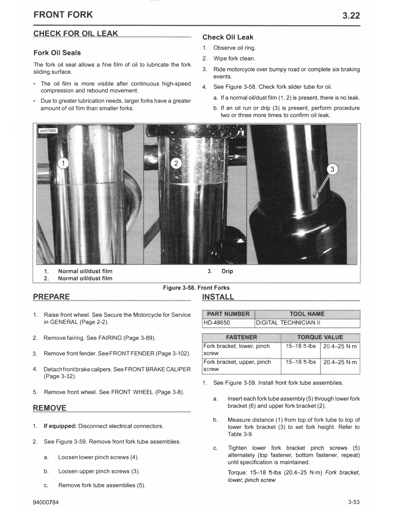
                                                                    4.        See Figure 3-58. Check fork slider tube for oil.
  compression and rebound movement.
• Due to greater lubrication needs, larger forks have a greater               a. If a normal oil/dust film (1, 2) is present, there is no leak.
  amount of oil film than smaller forks.                                      b. If an oil run or drip (3) is present, perform procedure
                                                                                 two or three more times to confirm oil leak.

     1.   Normal oil/dust film                                           3.        Drip
     2.   Normal oil/dust film
                                                     Figure 3-58. Front Forks
PREPARE                                                             INSTALL

1.   Raise front wheel. See Secure the Motorcycle for Service            PART NUMBER                           TOOL NAME
     in GENERAL (Page 2-2).                                         HD-48650                     DIGITAL TECHNICIAN II

2.   Remove fairing. See FAIRING (Page 3-89).                                       FASTENER                       TORQUE VALUE
                                                                    Fork bracket, lower, pinch                15-18 ft-lbs    20.4-25 N·m
3.   Remove front fender. See FRONT FENDER (Page 3-102).            screw
                                                                    Fork bracket, upper, pinch               15-18 ft-lbs     20.4-25 N·m
4.   Detach front brake calipers. See FRONT BRAKE CALIPER           screw
     (Page 3-32).
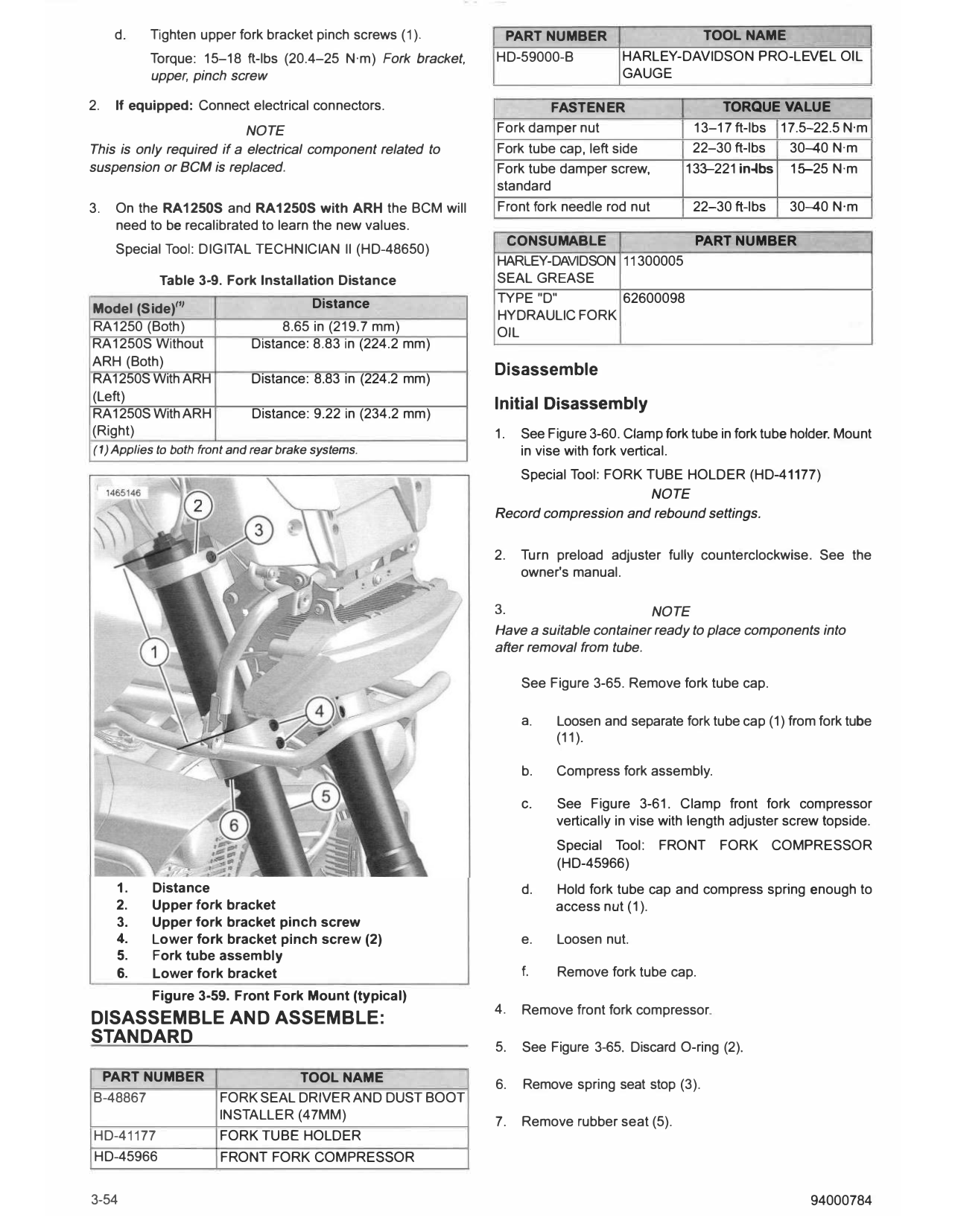
                                                                    1.        See Figure 3-59. Install front fork tube assemblies.
5.   Remove front wheel. See FRONT WHEEL (Page 3-8).
                                                                              a.     Insert each fork tube assembly (5) through lower fork
REMOVE                                                                               bracket (6) and upper fork bracket (2).

                                                                              b.     Measure distance (1) from top of fork tube to top of
1.   If equipped: Disconnect electrical connectors.                                  lower fork bracket (3) to set fork height. Refer to
                                                                                     Table 3-9.
2.   See Figure 3-59. Remove front fork tube assemblies.
                                                                              c.     Tighten lower fork bracket pinch screws (5)
     a.   Loosen lower pinch screws (4).                                             alternately (top fastener, bottom fastener, repeat)
                                                                                     until specification is maintained.
     b.   Loosen upper pinch screws (3).                                             Torque: 15-18 ft-lbs (20.4-25 N·m) Fork bracket,
                                                                                     lower, pinch screw
     c.   Remove fork tube assemblies (5).

94000784                                                                                                                                 3-53
     d.   Tighten upper fork bracket pinch screws (1 ).       PART NUMBER                   TOOL NAME
          Torque: 15-18 ft-lbs (20.4-25 N·m) Fork bracket,   HD-59000-B            HARLEY-DAVIDSON PRO-LEVEL OIL
          upper, pinch screw                                                       GAUGE

2.   If equipped: Connect electrical connectors.                      FASTENER                    TORQUE VALUE
                           NOTE                              Fork damper nut                  13-17 ft-lbs 17.5-22.5 N·m
This is only required if a electrical component related to   Fork tube cap, left side         22-30 ft-lbs  30--40 N·m
suspension or BCM is replaced.                               Fork tube damper screw,         133-221 in-lbs 15-25 N·m
                                                             standard
3.   On the RA1250S and RA1250S with ARH the BCM will        Front fork needle rod nut         22-30 ft-lbs    30-40 N·m
     need to be recalibrated to learn the new values.
                                                               CONSUMABLE             PART NUMBER
     Special Tool: DIGITAL TECHNICIAN II (HD-48650)
                                                             HARLEY-DAVIDSON 11300005
            Table 3-9. Fork Installation Distance            SEAL GREASE
                                        Distance             T YPE "D"       62600098
Model (Side)'''                                              HYDRAULIC FORK
RA1250 (Both)                     8.65 in (219.7 mm)         OIL
RA1250S Without              Distance: 8.83 in (224.2 mm)
ARH (Both)
                                                             Disassemble
RA1250S With ARH             Distance: 8.83 in (224.2 mm)
(Left)
                                                             Initial Disassembly
RA1250S With ARH             Distance: 9.22 in (234.2 mm)
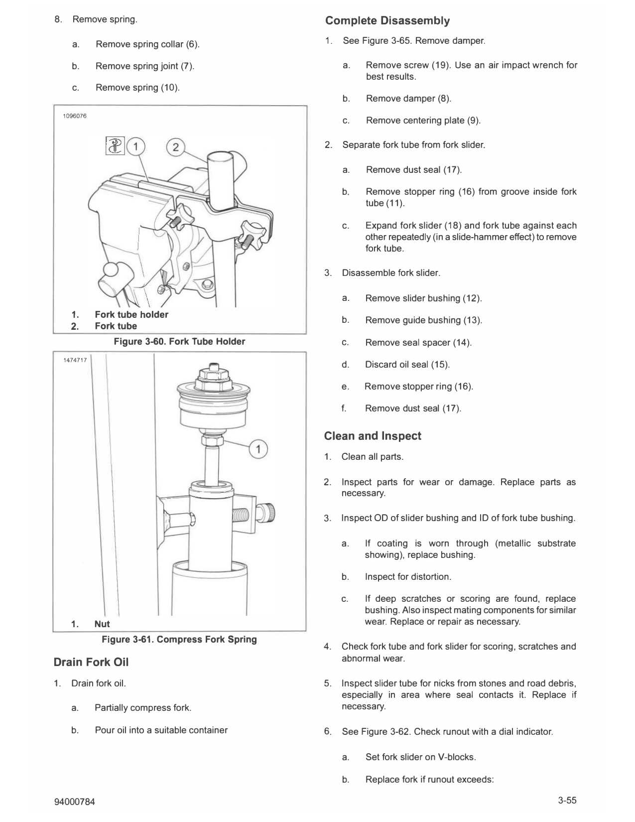
(Right)                                                      1.   See Figure 3-60. Clamp fork tube in fork tube holder. Mount
(1) Applies to both front and rear brake systems.                 in vise with fork vertical.
                                                                Special Tool: FORK T UBE HOLDER (HD-41177)
                                                                                    NOTE
                                                             Record compression and rebound settings.

                                                             2.   Turn preload adjuster fully counterclockwise. See the
                                                                  owner's manual.

                                                             3.                       NOTE
                                                             Have a suitable container ready to place components into
                                                             after removal from tube.

                                                                  See Figure 3-65. Remove fork tube cap.

                                                                  a.    Loosen and separate fork tube cap (1) from fork tube
                                                                        (11).

                                                                  b.    Compress fork assembly.

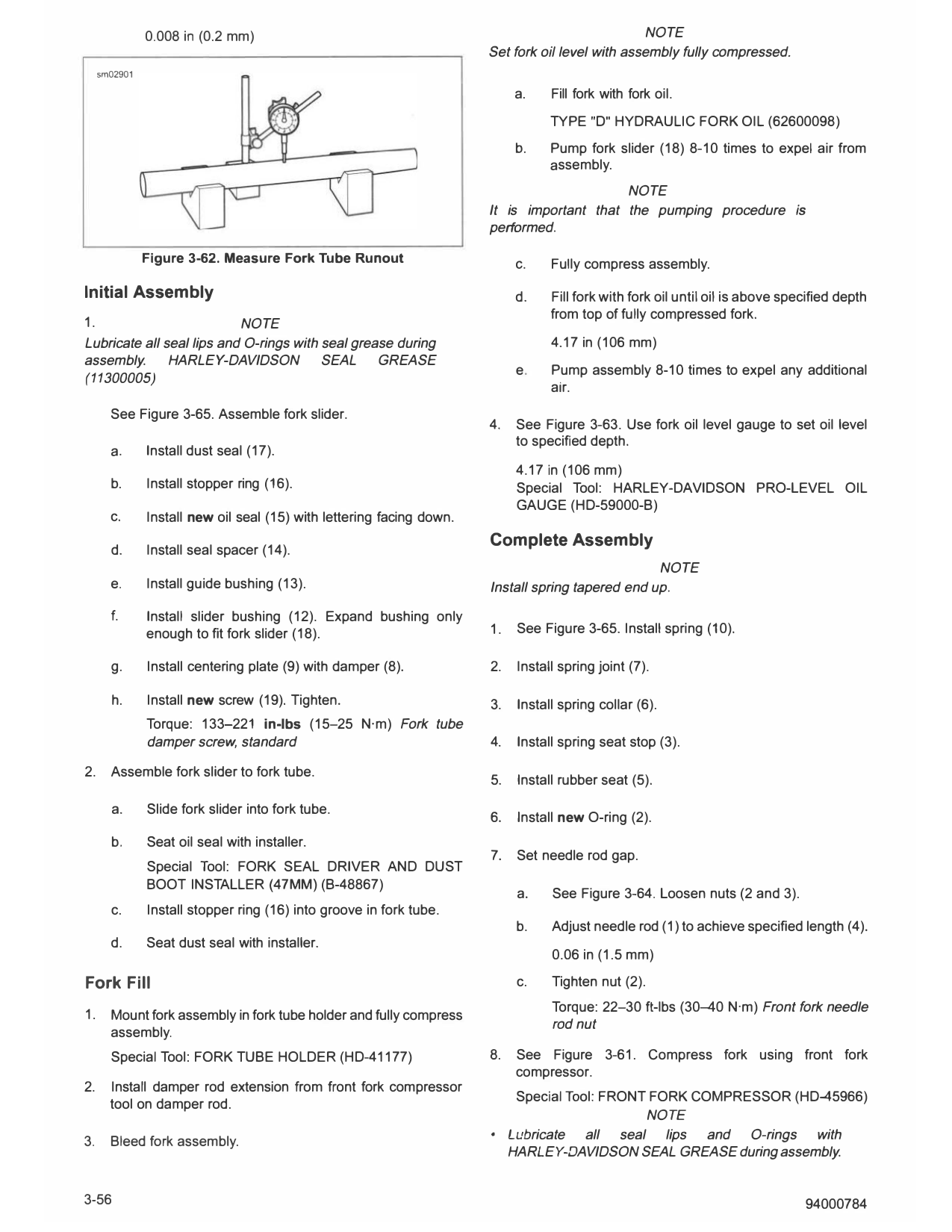
                                                                  c.    See Figure 3-61. Clamp front fork compressor
                                                                        vertically in vise with length adjuster screw topside.
                                                                        Special Tool:    FRONT     FORK COMPRESSOR
                                                                        (HD-45966)
     1.   Distance                                                d.   Hold fork tube cap and compress spring enough to
     2.   Upper fork bracket                                           access nut (1).
     3.   Upper fork bracket pinch screw
     4.   Lower fork bracket pinch sc rew (2)                     e.    Loosen nut.
     5.   Fork tube assembly
     6.   Lower fork bracket                                      f.    Remove fork tube cap.
          Figure 3-59. Front Fork Mount (typical)
                                                             4.   Remove front fork compressor.
DISASSEMBLE AND ASSEMBLE:
STANDARD                                                     5.   See Figure 3-65. Discard O-ring (2).

 PART NUMBER                      TOOL NAME
                                                             6.   Remove spring seat stop (3).
B-48867                FORK SEAL DRIVER AND DUST BOOT
                       INSTALLER (47MM)                      7.   Remove rubber seat (5).
HD-41177               FORK TUBE HOLDER
HD-45966               FRONT FORK COMPRESSOR

3-54                                                                                                               94000784
8.     Remove spring.                                Complete Disassembly

       a.      Remove spring collar (6).             1.   See Figure 3-65. Remove damper.

       b.      Remove spring joint (7).                   a.    Remove screw (19). Use an air impact wrench for
                                                                best results.
       c.      Remove spring (10).
                                                          b.    Remove damper (8).
     1096076
                                                          c.    Remove centering plate (9).

                                                     2.   Separate fork tube from fork slider.

                                                          a.    Remove dust seal (17).

                                                          b.    Remove stopper ring (16) from groove inside fork
                                                                tube (11).

                                                          c.    Expand fork slider (18) and fork tube against each
                                                                other repeatedly (in a slide-hammer effect) to remove
                                                                fork tube.

                                                     3.   Disassemble fork slider.

                                                          a.    Remove slider bushing (12).
       1.      Fork tube holder
                                                          b.    Remove guide bushing (13).
       2.      Fork tube
                     Figure 3-60. Fork Tube Holder        C.    Remove seal spacer (14).
     1474717
                                                          d.    Discard oil seal (15).

                                                          e.    Remove stopper ring (16).

                                                          f.    Remove dust seal (17).

                                                     Clean and Inspect
                                                     1.   Clean all parts.

                                                     2.   Inspect parts for wear or damage. Replace parts as
                                                          necessary.

                                                     3.   Inspect OD of slider bushing and ID of fork tube bushing.

                                                          a.    If coating is worn through (metallic substrate
                                                                showing), replace bushing.

                                                          b.    Inspect for distortion.

                                                          c.    If deep scratches or scoring are found, replace
                                                                bushing. Also inspect mating components for similar
       1.      Nut                                              wear. Replace or repair as necessary.
                Figure 3-61. Compress Fork Spring
                                                     4.   Check fork tube and fork slider for scoring, scratches and
                                                          abnormal wear.
Drain Fork Oil
1.     Drain fork oil.                               5.   Inspect slider tube for nicks from stones and road debris,
                                                          especially in area where seal contacts it. Replace if
       a.      Partially compress fork.                   necessary.

       b.      Pour oil into a suitable container    6.   See Figure 3-62. Check runout with a dial indicator.

                                                          a.    Set fork slider on V-blocks.

                                                          b.    Replace fork if runout exceeds:

94000784                                                                                                         3-55
               0.008 in (0.2 mm)                                                                  NOTE
                                                                       Set fork oil level with assembly fully compressed.
     sm02901

                                                                            a.    Fill fork with fork oil.
                                                                                  T YPE "D" HYDRAULIC FORK OIL (62600098)
                                                                            b.    Pump fork slider (18) 8-10 times to expel air from
                                                                                  assembly.
                                                                                            NOTE
                                                                       It is important that the pumping procedure is
                                                                       performed.

               Figure 3-62. Measure Fork Tube Runout                        c.    Fully compress assembly.

Initial Assembly                                                            d.    Fill fork with fork oil until oil is above specified depth
                                                                                  from top of fully compressed fork.
1.                         NOTE
Lubricate all seal lips and O-rings with seal grease during                       4.17 in (106 mm)
assembly.      HARLEY-DAVIDSON           SEAL     GREASE
                                                                            e.    Pump assembly 8-10 times to expel any additional
(11300005)
                                                                                  air.
       See Figure 3-65. Assemble fork slider.
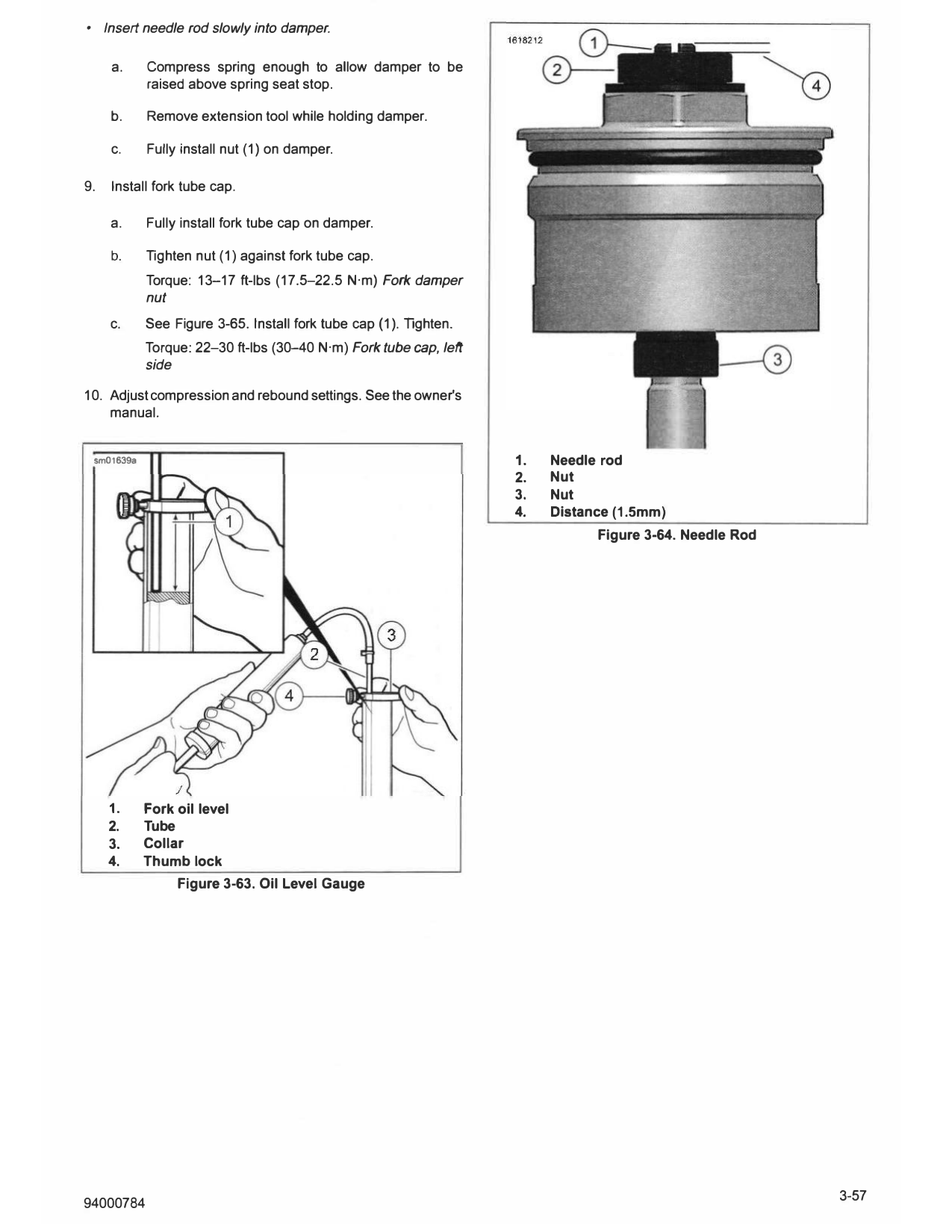
                                                                       4.   See Figure 3-63. Use fork oil level gauge to set oil level
                                                                            to specified depth.
       a.      Install dust seal (17).
                                                                            4.17 in (106 mm)
       b.      Install stopper ring (16).                                   Special Tool: HARLEY-DAVIDSON PRO-LEVEL OIL
                                                                            GAUGE (HD-59000-B)
       c.      Install new oil seal (15) with lettering facing down.
                                                                       Complete Assembly
       d.      Install seal spacer (14).
                                                                                                   NOTE
       e.      Install guide bushing (13).                             Install spring tapered end up.

       f.      Install slider bushing (12). Expand bushing only
               enough to fit fork slider (18).                         1.   See Figure 3-65. Install spring (10).

       g.      Install centering plate (9) with damper (8).            2.   Install spring joint (7).

       h.      Install new screw (19). T ighten.                       3.   Install spring collar (6).
               Torque: 133-221 in-lbs (15-25 N·m) Fork tube
               damper screw, standard                                  4.   Install spring seat stop (3).

2.     Assemble fork slider to fork tube.
                                                                       5.   Install rubber seat (5).

       a.      Slide fork slider into fork tube.
                                                                       6.   Install new O-ring (2).
       b.      Seat oil seal with installer.
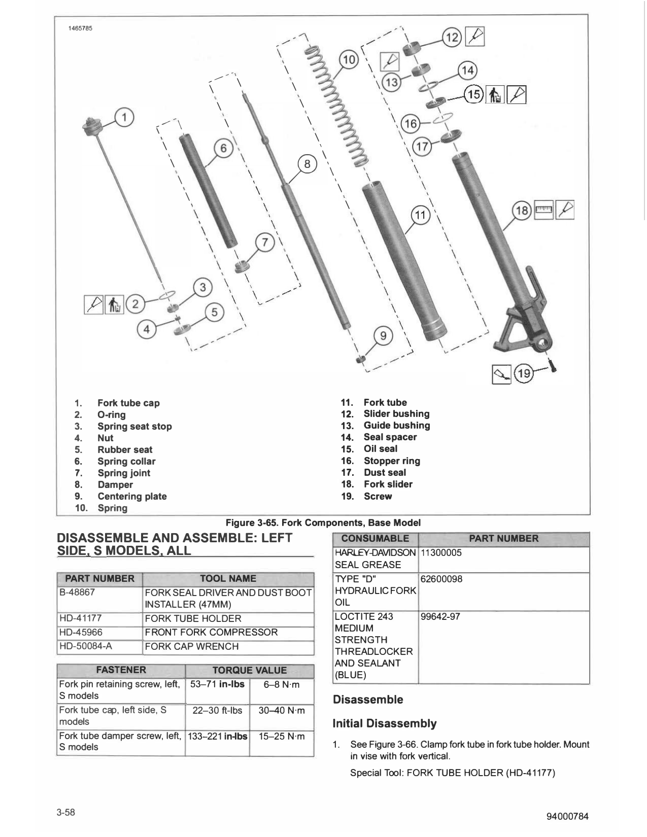
                                                                       7.   Set needle rod gap.
               Special Tool: FORK SEAL DRIVER AND DUST
               BOOT INSTALLER (47MM) (B-48867)
                                                                            a.    See Figure 3-64. Loosen nuts (2 and 3).
       c.      Install stopper ring (16) into groove in fork tube.
                                                                            b.    Adjust needle rod (1) to achieve specified length (4).
       d.      Seat dust seal with installer.
                                                                                  0.06 in (1.5 mm)

Fork Fill                                                                   c.    Tighten nut (2).
                                                                                  Torque: 22-30 ft-lbs (30-40 N·m) Front fork needle
1.     Mount fork assembly in fork tube holder and fully compress
                                                                                  rod nut
       assembly.
       Special Tool: FORK TUBE HOLDER (HD-41177)                       8.   See Figure 3-61. Compress fork using front fork
                                                                            compressor.
2.     Install damper rod extension from front fork compressor
                                                                          Special Tool: FRONT FORK COMPRESSOR (HD-45966)
       tool on damper rod.
                                                                                              NOTE
                                                                       • Lubricate   all seal lips and O-rings with
3.     Bleed fork assembly.
                                                                         HARLEY-DAVIDSON SEAL GREASE during assembly.

3-56                                                                                                                            94000784
•    Insert needle rod slowly into damper.

       a.      Compress spring enough to allow damper to be
               raised above spring seat stop.

       b.      Remove extension tool while holding damper.

       c.      Fully install nut (1) on damper.

9.     Install fork tube cap.

       a.      Fully install fork tube cap on damper.

       b.      Tighten nut (1) against fork tube cap.
               Torque: 13-17 ft-lbs (17.5-22.5 N·m) Fork damper
               nut
       c.      See Figure 3-65. Install fork tube cap (1). Tighten.
               Torque: 22-30 ft-lbs (30-40 N·m) Fork tube cap, left
               side

10. Adjust compression and rebound settings. See the owner's
    manual.

    sm01639a                                                          1.   Needle rod
                                                                      2.   Nut
                                                                      3.   Nut
                                                                      4.   Distance (1.5mm)
                                                                                 Figure 3-64. Needle Rod

      1.       Fork oil level
      2.       Tube
      3.       Collar
      4.       Thumb lock
                    Figure 3-63. Oil Level Gauge

  1465785

                                               , .,,.-
                                                         ,   ·,           \
                                                                  \           \
                                               \
                                                   \                              \
                            .,,.-
                                    \                    \                            \
                        \
                                                                                          \
                            \

                                                                           ft\
                                                                                              \

                                \
                                    \
                                                                                                   \
                                        \
                                                                                                       \

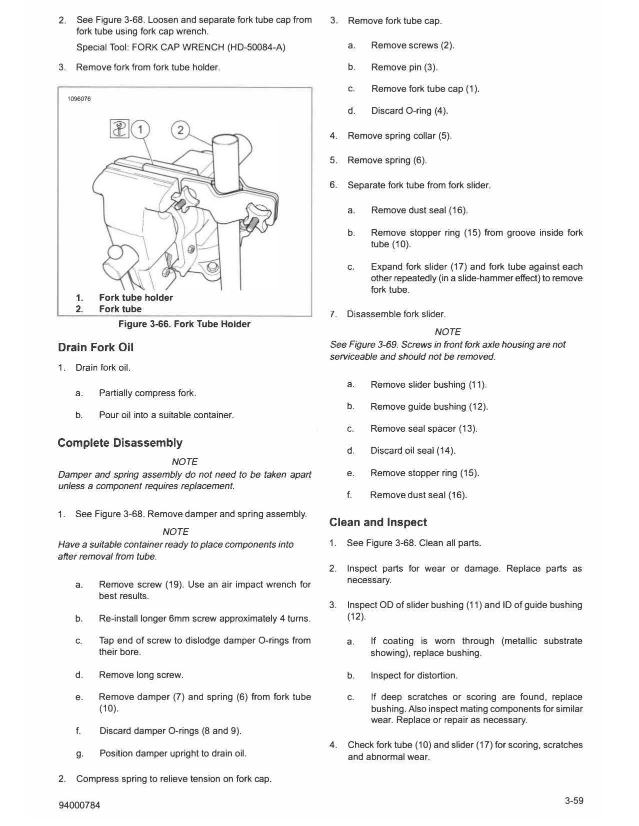
   1.       Fork tube cap                                                                              11.    Fork tube
   2.       O-ring                                                                                     12.    Slider bushing
   3.       Spring seat stop                                                                           13.    Guide bushing
   4.       Nut                                                                                        14.    Seal spacer
   5.       Rubber seat                                                                                15.    Oil seal
   6.       Spring collar                                                                              16.    Stopper ring
   7.       Spring joint                                                                               17.    Dust seal
   8.       Damper                                                                                     18.    Fork slider
   9.       Centering plate                                                                            19.    Screw
   10.      Spring
                                                         Figure 3-65. Fork Components, Base Model
DISASSEMBLE AND ASSEMBLE: LEFT                                                                      CONSUMABLE             PART NUMBER
SIDE. S MODELS. ALL                                                                               HARLEY-DAVIDSON 11300005
                                                                                                  SEAL GREASE
 PART NUMBER                    TOOL NAME                                                         TYPE "D"        62600098
B-48867               FORK SEAL DRIVER AND DUST BOOT                                              HYDRAULIC FORK
                      INSTALLER (47MM)                                                            OIL
HD-41177              FORK TUBE HOLDER                                                            LOCTITE 243     99642-97
HD-45966              FRONT FORK COMPRESSOR                                                       MEDIUM
                                                                                                  STRENGTH
HD-50084-A            FORK CAP WRENCH
                                                                                                  THREADLOCKER
                                                                                                  AND SEALANT
         FASTENER                               TORQUE VALUE
                                                                                                  (BLUE)
Fork pin retaining screw, left,             53-71 in-lbs 6-8 N·m
S models
                                                                                                  Disassemble
Fork tube cap, left side, S    22-30 ft-lbs                           30-40 N·m
models                                                                                            Initial Disassembly
Fork tube damper screw, left, 133-221 in-lbs                          15-25 N·m
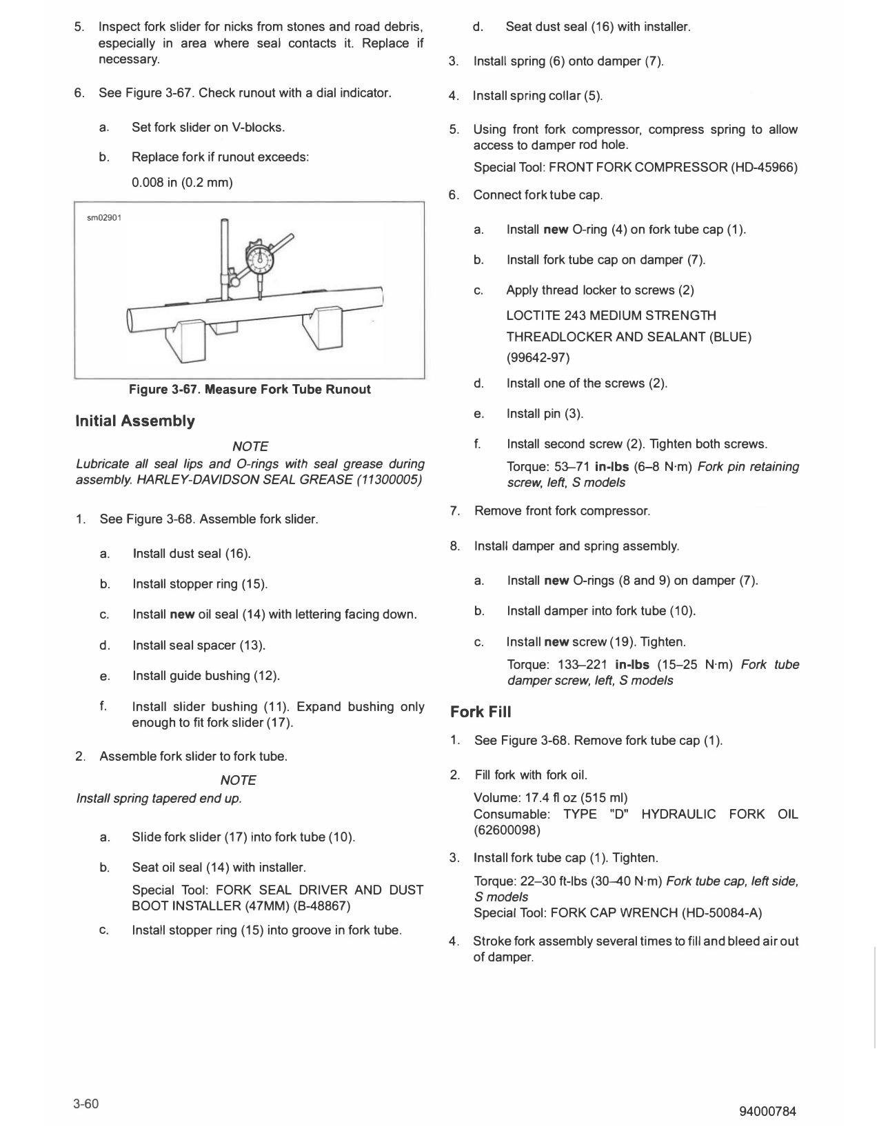
S models                                                                                          1.       See Figure 3-66. Clamp fork tube in fork tube holder. Mount
                                                                                                           in vise with fork vertical.
                                                                                                           S pecial Tool: FORK TUBE HOLDER (HD-41177)

3-58                                                                                                                                                       94000784
2.     See Figure 3-68. Loosen and separate fork tube cap from      3.   Remove fork tube cap.
       fork tube using fork cap wrench.
       Special Tool: FORK CAP WRENCH (HD-50084-A)                        a.   Remove screws (2).

3.     Remove fork from fork tube holder.                                b.   Remove pin (3).

                                                                         C.    Remove fork tube cap (1).
     1096076

                                                                         d.   Discard O-ring (4).

                                                                    4.   Remove spring collar (5).

                                                                    5.   Remove spring (6).

                                                                    6.   Separate fork tube from fork slider.

                                                                         a.   Remove dust seal (16).

                                                                         b.   Remove stopper ring (15) from groove inside fork
                                                                              tube (10).

                                                                         c.   Expand fork slider (17) and fork tube against each
                                                                              other repeatedly (in a slide-hammer effect) to remove
                                                                              fork tube.
       1.      Fork tube holder
       2.      Fork tube
                                                                    7.   Disassemble fork slider.
                    Figure 3-66. Fork Tube Holder
                                                                                            NOTE
Drain Fork Oil                                                      See Figure 3-69. Screws in front fork axle housing are not
                                                                    serviceable and should not be removed.
1.     Drain fork oil.
                                                                         a.   Remove slider bushing (11).
       a.      Partially compress fork.
                                                                         b.   Remove guide bushing (12).
       b.      Pour oil into a suitable container.
                                                                         C.   Remove seal spacer (13).
Complete Disassembly
                                                                         d.   Discard oil seal (14).
                          NOTE
Damper and spring assembly do not need to be taken apart                 e.   Remove stopper ring (15).
unless a component requires replacement.
                                                                         f.   Remove dust seal (16).

1.     See Figure 3-68. Remove damper and spring assembly.
                                                                    Clean and Inspect
                         NOTE
Have a suitable container ready to place components into            1.   See Figure 3-68. Clean all parts.
after removal from tube.
                                                                    2.   Inspect parts for wear or damage. Replace parts as
       a.      Remove screw (19). Use an air impact wrench for           necessary.
               best results.
                                                                    3.   Inspect OD of slider bushing (11) and ID of guide bushing
       b.      Re-install longer 6mm screw approximately 4 turns.        (12).

       c.      Tap end of screw to dislodge damper O-rings from          a.   If coating is worn through (metallic substrate
               their bore.                                                    showing), replace bushing.

       d.      Remove long screw.                                        b.   Inspect for distortion.

       e.      Remove damper (7) and spring (6) from fork tube           c.   If deep scratches or scoring are found, replace
               (10).                                                          bushing. Also inspect mating components for similar
                                                                              wear. Replace or repair as necessary.
       f.      Discard damper O-rings (8 and 9).
                                                                    4.   Check fork tube (10) and slider (17) for scoring, scratches
       g.      Position damper upright to drain oil.                     and abnormal wear.

2.     Compress spring to relieve tension on fork cap.

94000784                                                                                                                       3-59
5.     Inspect fork slider for nicks from stones and road debris,           d.    Seat dust seal (16) with installer.
       especially in area where seal contacts it. Replace if
       necessary.                                                      3.   Install spring (6) onto damper (7).

6.     See Figure 3-67. Check runout with a dial indicator.            4. Install spring collar (5).

       a.      Set fork slider on V-blocks.                            5.   Using front fork compressor, compress spring to allow
                                                                            access to damper rod hole.
       b.      Replace fork if runout exceeds:
                                                                            Special Tool: FRONT FORK COMPRESSOR (HD-45966)
               0.008 in (0.2 mm)
                                                                       6.   Connect fork tube cap.
     sm02901
                                                                            a.    Install new O-ring (4) on fork tube cap (1).

                                                                            b.    Install fork tube cap on damper (7).

                                                                            c.    Apply thread locker to screws (2)
                                                                                  LOCT ITE 243 MEDIUM STRENGTH
                                                                                  T HREADLOCKER AND SEALANT (BLUE)
                                                                                  (99642-97)

               Figure 3-67. Measure Fork Tube Runout                        d.    Install one of the screws (2).

                                                                            e.    Install pin (3).
Initial Assembly
                            NOTE                                            f.    Install second screw (2). Tighten both screws.
 Lubricate all seal lips and O-rings with seal grease during                      Torque: 53-71 in-lbs (6-8 N·m) Fork pin retaining
assembly. HARL EY-DAVIDSON SEAL GREASE (11300005)                                 screw, left, Smodels

                                                                       7.   Remove front fork compressor.
1.     See Figure 3-68. Assemble fork slider.

                                                                       8.   Install damper and spring assembly.
       a.      Install dust seal (16).

       b.      Install stopper ring (15).                                   a.    Install new O-rings (8 and 9) on damper (7).

       c.      Install new oil seal (14) with lettering facing down.        b.    Install damper into fork tube (10).

       d.      Install seal spacer (13).                                    c.    Install new screw (19). Tighten.
                                                                                  Torque: 133-221 in-lbs (15-25 N·m) Fork tube
       e.      Install guide bushing (12).                                        damper screw, left, Smodels
       f.      Install slider bushing (11). Expand bushing only        Fork Fill
               enough to fit fork slider (17).
                                                                       1.   See Figure 3-68. Remove fork tube cap (1).
2.     Assemble fork slider to fork tube.
                          NOTE                                         2.   Fill fork with fork oil.
Install spring tapered end up.                                              Volume: 17.4 fl oz (515 ml)
                                                                            Consumable: T YPE "D"          HYDRAULIC       FORK     OIL
                                                                            (62600098)
       a.      Slide fork slider (17) into fork tube (10).
                                                                       3.   Install fork tube cap (1). Tighten.
       b.      Seat oil seal (14) with installer.
                                                                            Torque: 22-30 ft-lbs (3�0 N·m) Fork tube cap, left side,
               Special Tool: FORK SEAL DRIVER AND DUST
                                                                             Smodels
               BOOT INSTALLER (47MM) (8-48867)
                                                                            Special Tool: FORK CAP WRENCH (HD-50084-A)
       c.      Install stopper ring (15) into groove in fork tube.
                                                                       4.   Stroke fork assembly several times to fill and bleed air out
                                                                            of damper.

   1466358

                                      \
                                          --\   I             --
                                                              \
                                                                  \
                                                                      \

                                                                          \
                                                                              \                                        \
                                                                                  \                                        \
                                                                                                                               I

                                                                                                                                   \
                                                                                      \
                                                                                          \
                                                                                              \
                                                                                                                                       I

                                                                                                                                           \
                                                                                                  \
                                                                                                      \            \               [ZJ\\ 1
                                                                                                          \                                    ',
                                                                                                              \\
                                                                                                               I
                                                                                                                       t:J?'-.- - _ _;.
                                                                                                                           \               -

                                                                          80!/-·@
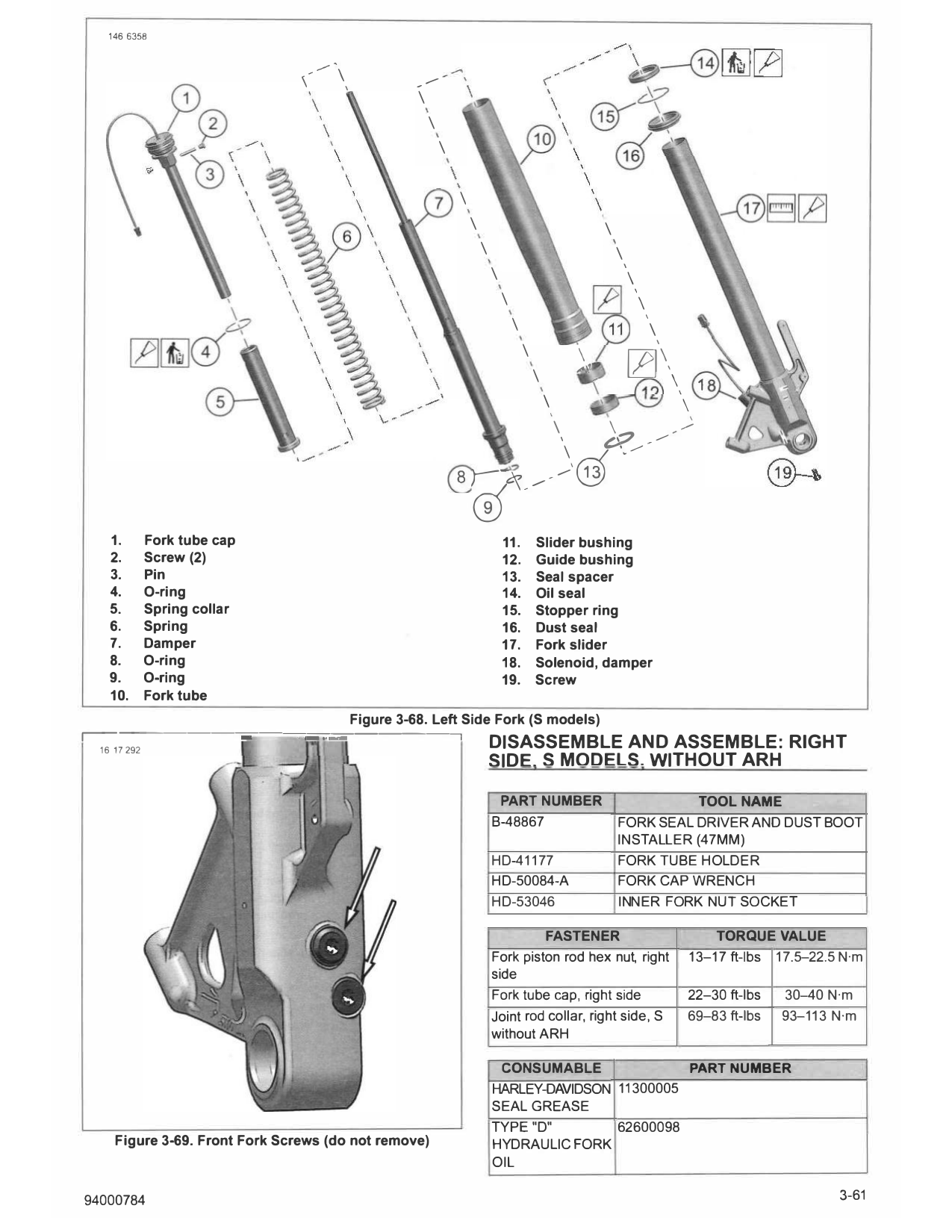
   1.    Fork tube cap                                                                    11.         Slider bushing
   2.    Screw (2)                                                                        12.         Guide bushing
   3.    Pin                                                                              13.         Seal spacer
   4.    O-ring                                                                           14.         Oil seal
   5.    Spring collar                                                                    15.         Stopper ring
   6.    Spring                                                                           16.         Dust seal
   7.    Damper                                                                           17.         Fork slider
   8.    O-ring                                                                           18.         Solenoid, damper
   9.    O-ring                                                                           19.         Screw
   10.   Fork tube
                                                    Figure 3-68. Left Side Fork (S models)
                         --------=-

r--1-617-29-2--------.=,          -==.--;;;;;;,-----,                                 DISASSEMBLE AND ASSEMBLE: RIGHT
                                                                                      SIDE. S MODELS. WITHOUT ARH

                                                                                       PART NUMBER                                     TOOL NAME
                                                                                      8-48867                              FORK SEAL DRIVER AND DUST BOOT
                                                                                                                           I N STALLER (47MM)
                                                                                      HD-41177                             FORK TUBE HOLDER
                                                                                      HD-50084-A                           FORK CAP WRENCH
                                                                                      HD-53046                             INNER FORK NUT SOCKET

                                                                                               FASTENER                                             TORQUE VALUE
                                                                                      Fork piston rod hex nut, right                            13-17 fl-lbs 17.5-22.5 N·m
                                                                                      side
                                                                                      Fork tube cap, right side                                 22-30 fl-lbs   30--40 N·m
                                                                                      Joint rod collar, right side, S                           69-83 fl-lbs   93-113 N·m
                                                                                      without ARH

                                                                                        CONSUMABLE             PART NUMBER
                                                                                      HARLEY-DAVIDSON 11300005
                                                                                      SEAL GREASE
                                                                                      T Y PE "D"      62600098
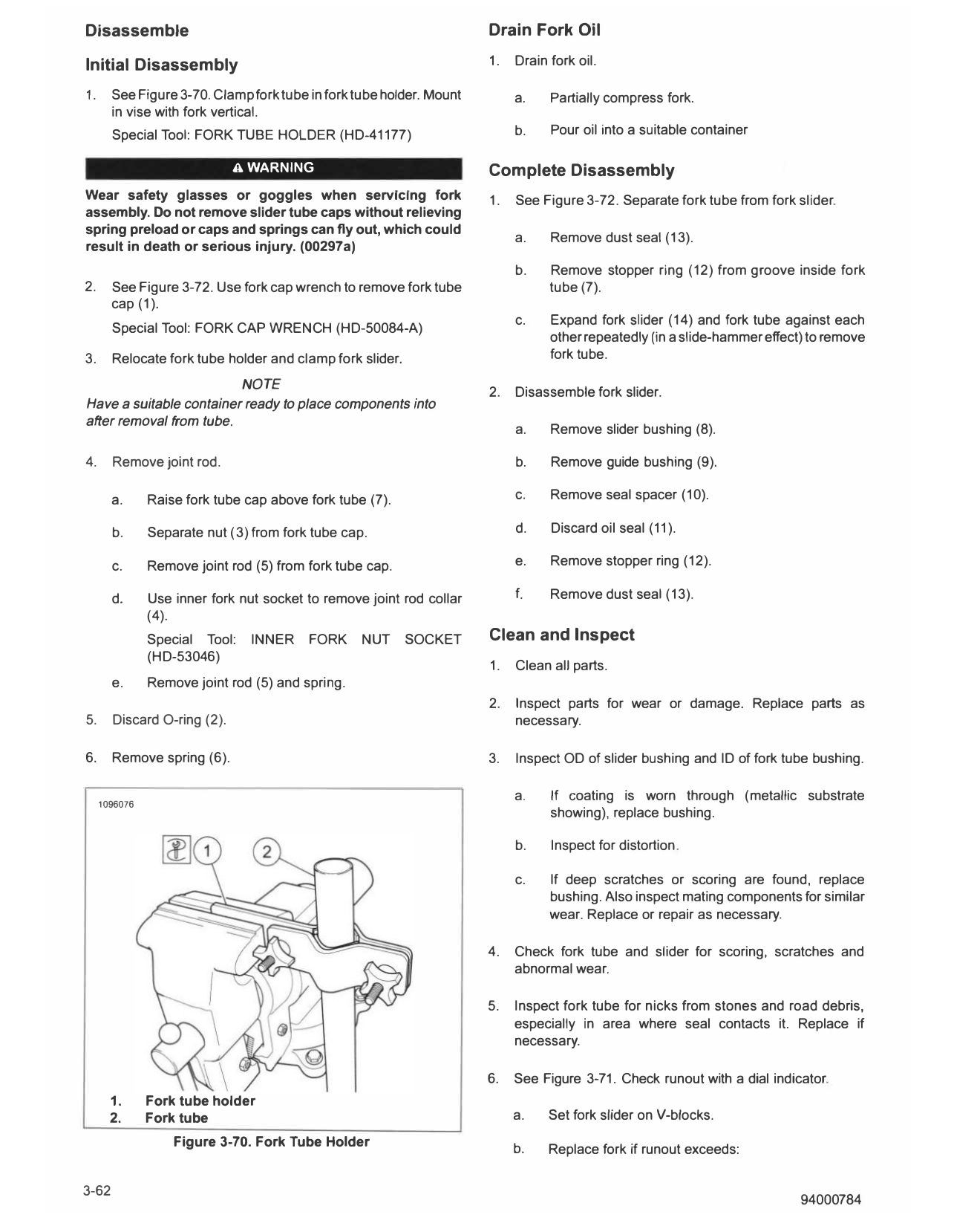
    Figure 3-69. Front Fork Screws (do not remove)                                    HYDRAULIC FORK
                                                                                      OI L

94000784                                                                                                                                                              3-61
Disassemble                                                           Drain Fork Oil

Initial Disassembly                                                   1.   Drain fork oil.

1.     See Figure 3-70. Clamp fork tube in fork tube holder. Mount         a.    Partially compress fork.
       in vise with fork vertical.
       Special Tool: FORK T UBE HOLDER (HD-41177)                          b.    Pour oil into a suitable container

                             A WARNING                                Complete Disassembly
Wear safety glasses or goggles when servicing fork                    1.   See Figure 3-72. Separate fork tube from fork slider..
assembly. Do not remove slider tube caps without relieving
spring preload or caps and springs can fly out, which could
                                                                           a.    Remove dust seal (13).
result in death or serious injury. (00297a)
                                                                           b.    Remove stopper ring (12) from groove inside fork
2.     See Figure 3-72. Use fork cap wrench to remove fork tube                  tube (7).
       cap (1 ).
                                                                           c.    Expand fork slider (14) and fork tube against each
       Special Tool: FORK CAP WRENCH (HD-50084-A)
                                                                                 other repeatedly (in a slide-hammer effect) to remove
3.     Relocate fork tube holder and clamp fork slider.                          fork tube.

                         NOTE                                         2.   Disassemble fork slider.
Have a suitable container ready to place components into
after removal from tube.
                                                                           a.    Remove slider bushing (8).

4.     Remove joint rod.                                                   b.    Remove guide bushing (9).

       a.      Raise fork tube cap above fork tube (7).                    C.    Remove seal spacer (10).

       b.      Separate nut (3) from fork tube cap.                        d.    Discard oil seal (11 ).

       c.      Remove joint rod (5) from fork tube cap.                    e.    Remove stopper ring (12).

       d.      Use inner fork nut socket to remove joint rod collar        f.    Remove dust seal (13).
               (4).
               Special Tool:    INNER    FORK     NUT     SOCKET      Clean and Inspect
               (HD-53046)
                                                                      1.   Clean all parts.
       e.      Remove joint rod (5) and spring.
                                                                      2.   Inspect parts for wear or damage. Replace parts as
5.     Discard O-ring (2).                                                 necessary.

6.     Remove spring (6).                                             3.   Inspect OD of slider bushing and ID of fork tube bushing.

                                                                           a.    If coating is worn through (metallic substrate
     1096076
                                                                                 showing), replace bushing.

                                                                           b.    Inspect for distortion.

                                                                           c.    If deep scratches or scoring are found, replace
                                                                                 bushing. Also inspect mating components for similar
                                                                                 wear. Replace or repair as necessary.

                                                                      4.   Check fork tube and slider for scoring, scratches and
                                                                           abnormal wear.

                                                                      5.   Inspect fork tube for nicks from stones and road debris,
                                                                           especially in area where seal contacts it. Replace if
                                                                           necessary.

                                                                      6.   See Figure 3-71. Check runout with a dial indicator.
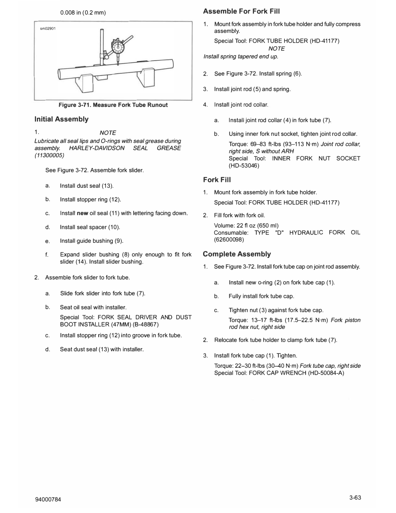
       1.      Fork tube holder
       2.      Fork tube                                                   a.    Set fork slider on V-blocks.
                   Figure 3-70. Fork Tube Holder
                                                                           b.    Replace fork if runout exceeds:

               0.008 in (0.2 mm)                                       Assemble For Fork Fill
                                                                       1.   Mount fork assembly in fork tube holder and fully compress
     sm02901
                                                                            assembly.
                                                                            Special Tool: FORK TUBE HOLDER (HD-41177)
                                                                                                 NOTE
                                                                       Install spring tapered end up.

                                                                       2.   See Figure 3-72. Install spring (6).

                                                                       3.   Install joint rod (5) and spring.

               Figure 3-71. Measure Fork Tube Runout                   4.   Install joint rod collar.

Initial Assembly                                                            a.    Install joint rod collar (4) in fork tube (7).

1.                              NOTE                                        b.    Using inner fork nut socket, tighten joint rod collar.
Lubricate all seal lips and O-rings with seal grease during
                                                                                  Torque: 69--83 ft-lbs (93--113 N·m) Joint rod collar,
assembly.      HARLEY-DAVIDSON           SEAL     GREASE
                                                                                  right side, S without ARH
(11300005)
                                                                                  Special Tool:         INNER    FORK     NUT      SOCKET
                                                                                  (HD-53046)
       See Figure 3-72. Assemble fork slider.
                                                                       Fork Fill
       a.      Install dust seal (13).
                                                                       1.   Mount fork assembly in fork tube holder.
       b.      Install stopper ring (12).
                                                                            Special Tool: FORK TUBE HOLDER (HD-41177)
       c.      Install new oil seal (11) with lettering facing down.   2.   Fill fork with fork oil.

       d.      Install seal spacer (10).                                    Volume: 22 fl oz (650 ml)
                                                                            Consumable: TYPE "D"             HYDRAULIC         FORK OIL
       e.      Install guide bushing (9).                                   (62600098)

       f.      Expand slider bushing (8) only enough to fit fork       Complete Assembly
               slider (14). Install slider bushing.
                                                                       1.   See Figure 3-72. Install fork tube cap on joint rod assembly.
2.     Assemble fork slider to fork tube.
                                                                            a.     Install new a-ring (2) on fork tube cap (1).
       a.      Slide fork slider into fork tube (7).
                                                                            b.    Fully install fork tube cap.
       b.      Seat oil seal with installer.                                c.    Tighten nut (3) against fork tube cap.
               Special Tool: FORK SEAL DRIVER AND DUST                            Torque: 13--17 ft-lbs (17.5--22.5 N·m) Fork piston
               BOOT IN STALLER (47MM) (B-48867)                                   rod hex nut, right side
       c.      Install stopper ring (12) into groove in fork tube.
                                                                       2.   Relocate fork tube holder to clamp fork tube (7).
       d.      Seat dust seal (13) with installer.
                                                                       3.   Install fork tube cap (1). Tighten.
                                                                            Torque: 22-30 ft-lbs (30--40 N·m) Fork tube cap, right side
                                                                            Special Tool: FORK CAP WRENCH (HD-50084-A)

94000784                                                                                                                              3-63
  1466362

                                           \
                                               \   I

                                                   \

         JD \ \
                                                       I

                                                           \
                                                               \
                                                               I

                                                                   \
                          I
            '             \
        &:,JD \
                                                                       I

                                                                           \

   0 '\ ,0 \                                           fe\
   [i] -\
                                                                               I

                                                                                   \
   [2]
                                                                                   I

                               \\
                                I
                                                                                       \
                                                                                       \

                                                                                           \
                                                                                               \
                                                                                                   \
                                                                                                       \

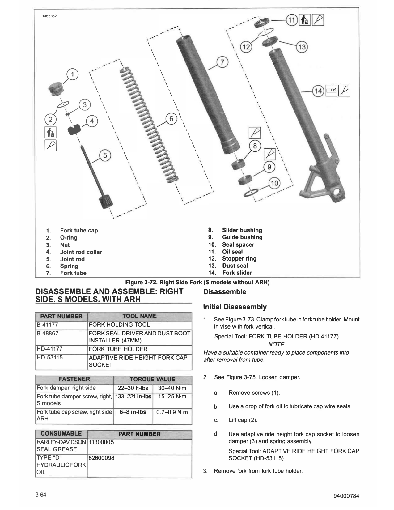
   1.       Fork tube cap                                                                              8.       Slider bushing
   2.       O-ring                                                                                     9.       Guide bushing
   3.       Nut                                                                                        10.      Seal spacer
   4.       Joint rod collar                                                                           11.      Oil seal
   5.       Joint rod                                                                                  12.      Stopper ring
   6.       Spring                                                                                     13.      Dust seal
   7.       Fork tube                                                                                  14.      Fork slider
                                    Figure 3-72. Right Side Fork (5 models without ARH)
DISASSEMBLE AND ASSEMBLE: RIGHT                                                                Disassemble
SIDE. S MODELS. WITH ARH
                                                                                               Initial Disassembly
 PART NUMBER                    TOOLNAME
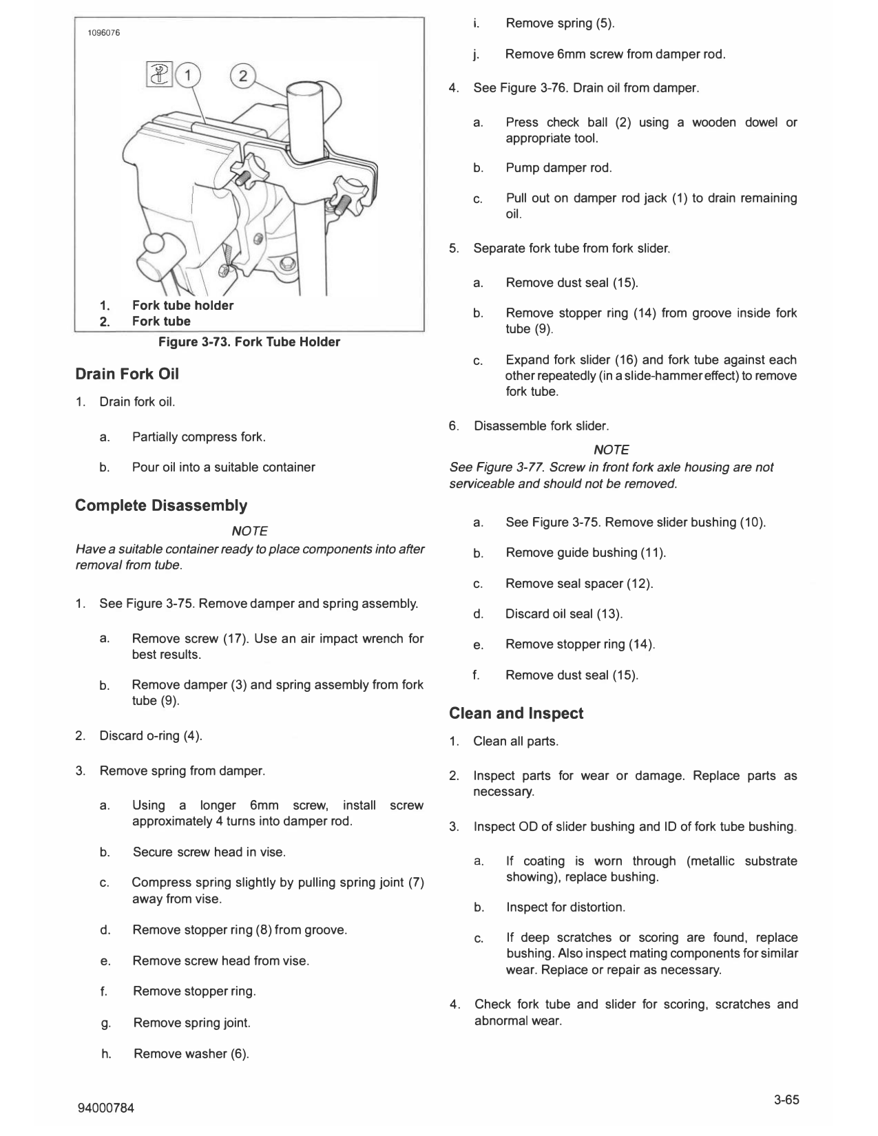
                                                                                               1.          See Figure 3-73. Clamp fork tube in fork tube holder. Mount
8-41177               FORK HOLDING TOOL                                                                    in vise with fork vertical.
8-48867               FORK SEAL DRIVER AND DUST BOOT
                                                                                                    Special Tool: FORK TUBE HOLDER (HD-41177)
                      INSTALLER (47MM)
                                                                                                                        NOTE
HD-41177              FORK TUBE HOLDER
                                                                                               Have a suitable container ready to place components into
HD-53115              ADAPTIVE RIDE HEIGHT FORK CAP                                            after removal from tube.
                      SOCKET

         FASTENER                   TORQUE VALUE                                               2.          See Figure 3-75. Loosen damper.
Fork damper, right side         22-30 fl-lbs  30-40 N·m
                                                                                                           a.     Remove screws (1).
Fork tube damper screw, right, 133-221 in-lbs 15--25 N·m
S models
                                                                                                           b.     Use a drop of fork oil to lubricate cap wire seals.
Fork tube cap screw, right side 6-8 in-lbs    0.7-0.9 N·m
ARH                                                                                                        c.     Lift cap (2).

 CONSUMABLE              PART NUMBER                                                                       d.     Use adaptive ride height fork cap socket to loosen
HARLEY-DAVIDSON 11300005                                                                                          damper (3) and spring assembly.
SEAL GREASE                                                                                                       Special Tool: ADAPTIVE RIDE HEIGHT FORK CAP
TYPE "D"        62600098                                                                                          SOCKET (HD-53115)
HYDRAULIC FORK
OIL                                                                                            3.          Remove fork from fork tube holder.

3-64                                                                                                                                                         94000784
                                                                           i.    Remove spring (5).
     1096076

                                                                           j.    Remove 6mm screw from damper rod.

                                                                      4.   See Figure 3-76. Drain oil from damper.

                                                                           a.    Press check ball (2) using a wooden dowel or
                                                                                 appropriate tool.

                                                                           b.    Pump damper rod.

                                                                           c.    Pull out on damper rod jack (1) to drain remaining
                                                                                 oil.

                                                                      5.   Separate fork tube from fork slider.

                                                                           a.    Remove dust seal (15).
       1.      Fork tube holder
                                                                           b.    Remove stopper ring (14) from groove inside fork
       2.      Fork tube
                                                                                 tube (9).
                   Figure 3-73. Fork Tube Holder
                                                                           c.    Expand fork slider (16) and fork tube against each
Drain Fork Oil                                                                   other repeatedly (in a slide-hammer effect) to remove
                                                                                 fork tube.
1.     Drain fork oil.
                                                                      6.   Disassemble fork slider.
       a.      Partially compress fork.
                                                                                              NOTE
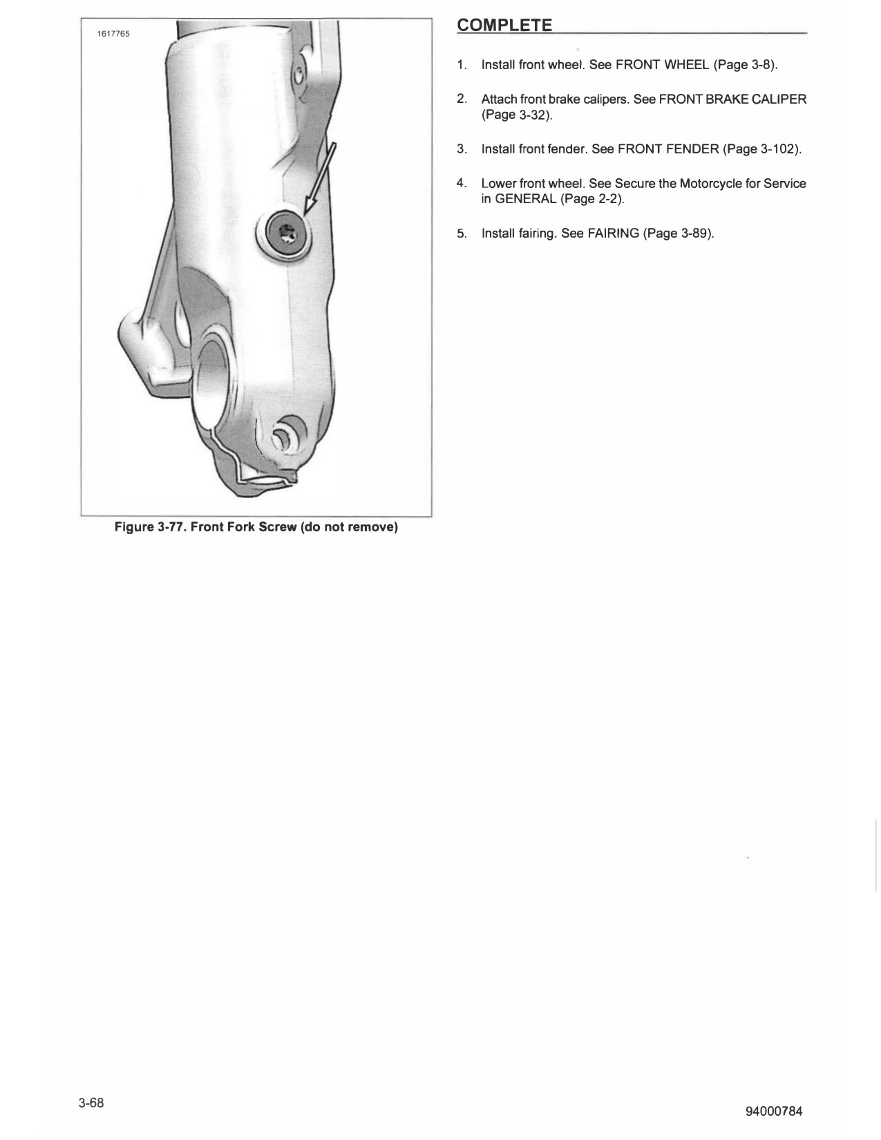
       b.      Pour oil into a suitable container                     See Figure 3-77. Screw in front fork axle housing are not
                                                                      serviceable and should not be removed.
Complete Disassembly
                                                                           a.    See Figure 3-75. Remove slider bushing (10).
                            NOTE
Have a suitable container ready to place components into after             b.    Remove guide bushing (11).
removal from tube.
                                                                           c.    Remove seal spacer (12).
1.     See Figure 3-75. Remove damper and spring assembly.
                                                                           d.    Discard oil seal (13).
       a.      Remove screw (17). Use an air impact wrench for                   Remove stopper ring (14).
                                                                           e.
               best results.
                                                                           f.    Remove dust seal (15).
       b.      Remove damper (3) and spring assembly from fork
               tube (9).
                                                                      Clean and Inspect
2.     Discard o-ring (4).                                            1.   Clean all parts.

3.     Remove spring from damper.                                     2.   Inspect parts for wear or damage. Replace parts as
                                                                           necessary.
       a.      Using a longer 6mm screw, install            screw
               approximately 4 turns into damper rod.                 3.   Inspect OD of slider bushing and ID of fork tube bushing.

       b.      Secure screw head in vise.
                                                                           a.    If coating is worn through (metallic substrate
       c.      Compress spring slightly by pulling spring joint (7)              showing), replace bushing.
               away from vise.
                                                                           b.    Inspect for distortion.
       d.      Remove stopper ring (8) from groove.
                                                                           c.    If deep scratches or scoring are found, replace
                                                                                 bushing. Also inspect mating components for similar
       e.      Remove screw head from vise.
                                                                                 wear. Replace or repair as necessary.
       f.      Remove stopper ring.
                                                                      4.   Check fork tube and slider for scoring, scratches and
       g.      Remove spring joint.                                        abnormal wear.

        h.     Remove washer (6).

5.     Inspect fork tube for nicks from stones and road debris,             b.    Turn ignition switch ON.
       especially in area where seal contacts it. Replace if
       necessary.                                                           c.    Retract damper rod jack.

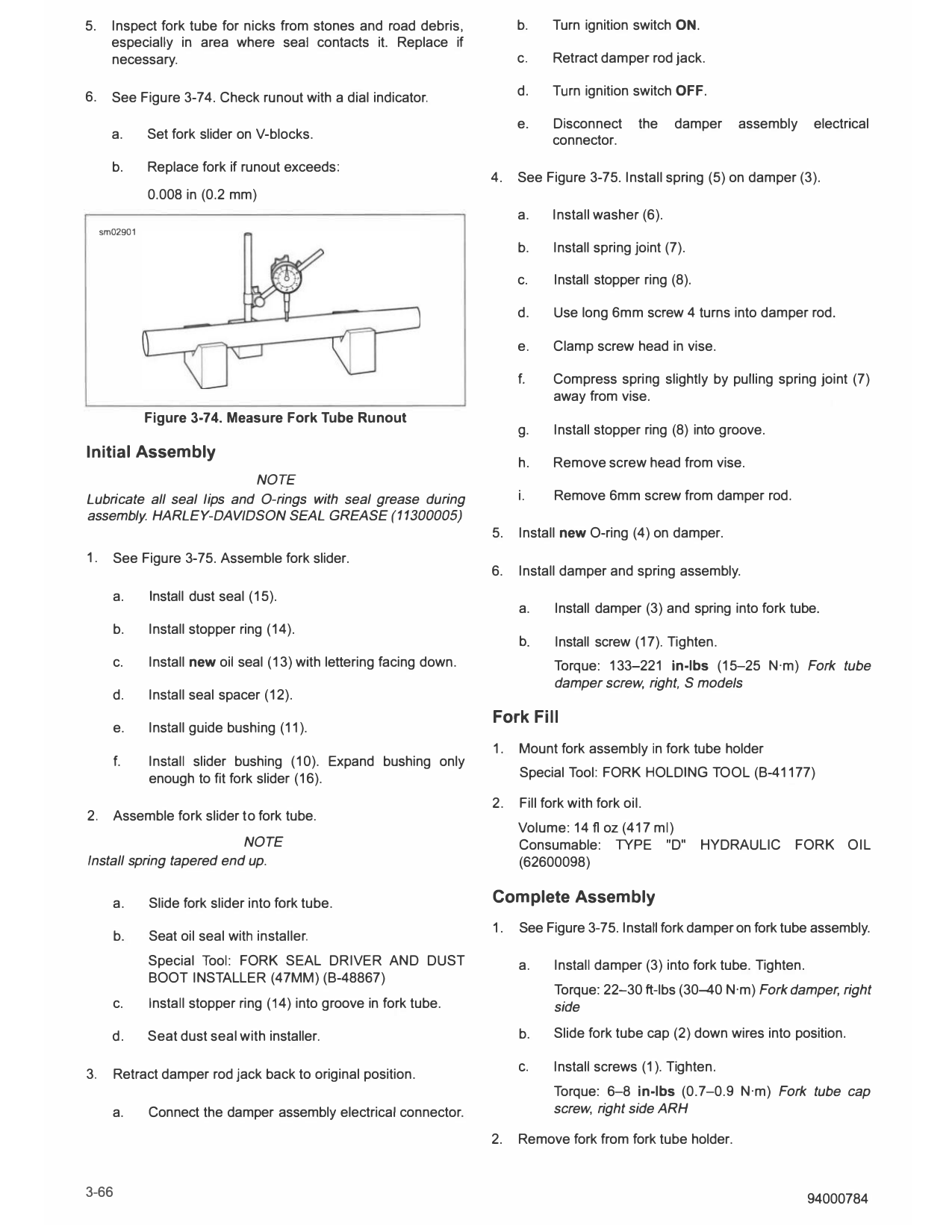
6.     See Figure 3-74. Check runout with a dial indicator.                 d.    Turn ignition switch OFF.

                                                                            e.    Disconnect       the   damper   assembly      electrical
       a.      Set fork slider on V-blocks.                                       connector.
       b.      Replace fork if runout exceeds:
                                                                       4.   See Figure 3-75. Install spring (5) on damper (3).
               0.008 in (0.2 mm)
                                                                            a.    Install washer (6).
     sm02901

                                                                            b.    Install spring joint (7).

                                                                            c.    Install stopper ring (8).

                                                                            d.    Use long 6mm screw 4 turns into damper rod.

                                                                            e.    Clamp screw head in vise.

                                                                            f.    Compress spring slightly by pulling spring joint (7)
                                                                                  away from vise.
               Figure 3-74. Measure Fork Tube Runout
                                                                            g.    Install stopper ring (8) into groove.
Initial Assembly
                                                                            h.    Remove screw head from vise.
                           NOTE
Lubricate all seal lips and O-rings with seal grease during                 i.    Remove 6mm screw from damper rod.
assembly. HARLEY-DAVIDSON SEAL GREASE (11300005)
                                                                       5.   Install new O-ring (4) on damper.
1.     See Figure 3-75. Assemble fork slider.
                                                                       6.   Install damper and spring assembly.
       a.      Install dust seal (15).
                                                                            a.    Install damper (3) and spring into fork tube.
       b.      Install stopper ring (14).
                                                                            b.    Install screw (17). Tighten.
       c.      Install new oil seal (13) with lettering facing down.              Torque: 133-221 in-lbs (15-25 N·m) Fork tube
                                                                                  damper screw, right, S models
       d.      Install seal spacer (12).
                                                                       Fork Fill
       e.      Install guide bushing (11).
                                                                       1.   Mount fork assembly in fork tube holder
       f.      Install slider bushing (10). Expand bushing only
               enough to fit fork slider (16).                              Special Tool: FORK HOLDING TOOL (B-41177)

                                                                       2.   Fill fork with fork oil.
2.     Assemble fork slider to fork tube.
                                                                            Volume: 14 fl oz (417 ml)
                          NOTE                                              Consumable: TYPE "D"              HYDRAULIC    FORK OIL
Install spring tapered end up.                                              (62600098)

       a.      Slide fork slider into fork tube.                       Complete Assembly
                                                                       1.   See Figure 3-75. Install fork damper on fork tube assembly.
       b.      Seat oil seal with installer.
               Special Tool: FORK SEAL DRIVER AND DUST                      a.    Install damper (3) into fork tube. Tighten.
               BOOT INSTALLER (47MM) (B-48867)
                                                                                  Torque: 22-30 ft-lbs (30-40 N·m) Fork damper, right
       c.      Install stopper ring (14) into groove in fork tube.                side

       d.      Seat dust seal with installer.                               b.    Slide fork tube cap (2) down wires into position.

                                                                            C.    Install screws (1). T ighten.
3.     Retract damper rod jack back to original position.
                                                                                  Torque: 6-8 in-lbs (0.7-0.9 N·m) Fork tube cap
       a.      Connect the damper assembly electrical connector.                  screw, right side ARH

                                                                       2.   Remove fork from fork tube holder.

3-66                                                                                                                            94000784
                                                                               \
                                                                                   \   I

                                                                                           \
                                                                                               \
                                                                               [2]\

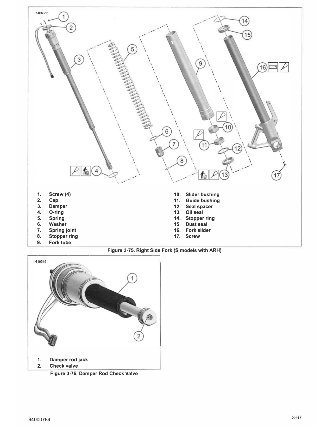
   1.   Screw (4)                                            10.   Slider bushing
   2.   Cap                                                  11.   Guide bushing
   3.   Damper                                               12.   Seal spacer
   4.   0-ring                                               13.   Oil seal
   5.   Spring                                               14.   Stopper ring
   6.   Washer                                               15.   Dust seal
   7.   Spring joint                                         16.   Fork slider
   8.   Stopper ring                                         17.   Screw
   9.   Fork tube
                                 Figure 3-75. Right Side Fork (S models with ARH)
�-----------,

   1.   Damper rod jack
   2.   Check valve
           Figure 3-76. Damper Rod Check Valve

94000784                                                                                           3-67
  1617765
                                                       COMPLETE

                                                       1.   Install front wheel. See FRONT WHEEL (Page 3-8).

                                                       2.   Attach front brake calipers. See FRONT BRAKE CALIPER
                                                            (Page 3-32).

                                                       3.   Install front fender. See FRONT FENDER (Page 3-102).

                                                       4.   Lower front wheel. See Secure the Motorcycle for Service
                                                            in GENERAL (Page 2-2).

                                                       5.   Install fairing. See FAIRING (Page 3-89).

       Figure 3-77. Front Fork Screw (do not remove)