3.20 Bleed Brakes
Fragment manuala — str. 127–129
📋 Tekst do skopiowania (OCR/wyszukiwanie)
BLEED BRAKES 3.20
DRAIN sm08416
PART NUMBER TOOL NAME
BB200A BASIC VACUUM BRAKE BLEEDER
NOTICE
-� �
DOT 4 brake fluid will damage painted and body panel
. 2
surfaces it comes in contact with. Always use caution and
\ v~
protect surfaces from spills whenever brake work is
performed. Failure to comply can result in cosmetic
damage. (00239c)
- I
NOTE
• For best results, use BASIC VACUUM BRAKE BLEEDER
(PART NUMBER: BB200A) to drain the brake systems. {\ '
• Both front and rear brake systems are affected when
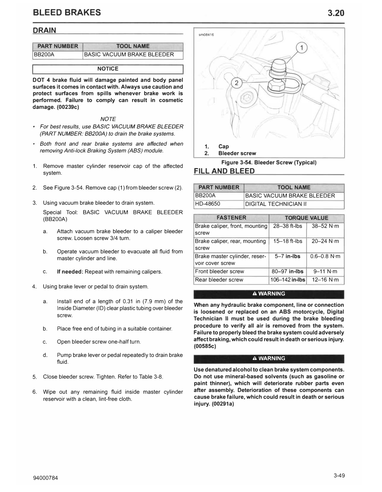
1. Cap
removing Anti-lock Braking System (ABS) module.
2. Bleeder screw
Figure 3-54. Bleeder Screw (Typical)
1. Remove master cylinder reservoir cap of the affected
system. FILL AND BLEED
2. See Figure 3-54. Remove cap (1) from bleeder screw (2). PART NUMBER TOOL NAME
BB200A BASIC VACUUM BRAKE BLEEDER
3. Using vacuum brake bleeder to drain system. HD-48650 DIGITAL TECHNICIAN II
Special Tool: BASIC VACUUM BRAKE BLEEDER
(BB200A) FASTENER TORQUE VALUE
Brake caliper, front, mounting 28-38 ft-lbs 38-52 N·m
a. Attach vacuum brake bleeder to a caliper bleeder screw
screw. Loosen screw 3/4 turn.
Brake caliper, rear, mounting 15-18 ft-lbs 20-24 N·m
screw
b. Operate vacuum bleeder to evacuate all fluid from
master cylinder and line. Brake master cylinder, reser- 5-7 in-lbs 0.6-0.8 N·m
voir cover screw
c. If needed: Repeat with remaining calipers. Front bleeder screw 80-97 in-lbs 9-11 N·m
Rear bleeder screw 106-142 in-lbs 12-16 N·m
4. Using brake lever or pedal to drain system.
A WARNING
a. Install end of a length of 0.31 in (7.9 mm) of the
When any hydraulic brake component, line or connection
Inside Diameter (ID) clear plastic tubing over bleeder
is loosened or replaced on an ABS motorcycle, Digital
screw.
Technician II must be used during the brake bleeding
procedure to verify all air is removed from the system.
b. Place free end of tubing in a suitable container.
Failure to properly bleed the brake system could adversely
c. Open bleeder screw one-half turn. affect braking, which could result in death or serious injury.
(00585c)
d. Pump brake lever or pedal repeatedly to drain brake
A WARNING
fluid.
Use denatured alcohol to clean brake system components.
5. Close bleeder screw. Tighten. Refer to Table 3-8. Do not use mineral-based solvents (such as gasoline or
paint thinner), which will deteriorate rubber parts even
6. Wipe out any remaining fluid inside master cylinder after assembly. Deterioration of these components can
reservoir with a clean, lint-free cloth. cause brake failure, which could result in death or serious
injury. (00291a)
94000784 3-49
A WARNING e. Repeat with remaining calipers.
Contact with DOT 4 brake fluid can have serious health 3. Again verify fluid in front and rear master cylinders are up
effects. Failure to wear proper skin and eye protection to specification.
could result in death or serious injury.
• If inhaled: Keep calm, remove to fresh air, seek medical 4. Have a helper compress brake lever or press on rear brake
attention. foot pedal, hold in compressed position.
• If on skin: Remove contaminated clothing. Rinse skin NOTE
immediately with plenty of water for 15-20 minutes. If Brake lever and foot pedal pressure must be maintained
irritation develops, seek medical attention. through steps 5-9.
• If in eyes: Wash affected eyes for at least 15 minutes
under running water with eye lids held open. If irritation 5. Loosen a bleeder screw on one of the calipers to relieve
develops, seek medical attention. pressure in system. Re-tighten bleeder screw.
• If swallowed: Rinse mouth and then drink plenty of
water. Do not induce vomiting. Contact Poison Control. 6. Remove brake caliper.
Immediate medical attention required.
a. Remove caliper mounting screws.
• See Safety Data Sheet (SDS) for more details available
at sds.harley-davidson.com b. Remove caliper.
(00240e)
c. With bleeder screw facing up, open caliper bleed
NOTICE screw.
DOT 4 brake fluid will damage painted and body panel d. Push pads apart until caliper pistons are fully
surfaces it comes in contact with. Always use caution and extended.
protect surfaces from spills whenever brake work is
performed. Failure to comply can result in cosmetic e. Close bleeder screw.
damage. (00239c)
f. Repeat steps with remaining calipers.
• If DOT 4 brake fluid contacts painted surfaces,
IM MEDIATE LY flush area with clear water. 7. Front brake caliper: Install caliper to axle holder. Do not
tighten.
NOTICE
Do not allow dirt or debris to enter the master cylinder 8. Rear brake caliper: Install brake caliper on caliper bracket
reservoir. Dirt or debris in the reservoir can cause improper with screws. Tighten.
operation and equipment damage. (00205c)
Torque: 15-18 ft-lbs (20-24 N·m) Brake caliper, rear,
mounting screw
Verify front brake hand lever and rear brake foot pedal have a
firm feel when applied. If not, bleed system as described. 9. Release pressure on lever or rear brake foot pedal.
NOTE
Bleed procedure
For dual front brake systems, first bleed from caliper that
1. Verify fluid in front and rear master cylinders are up to is furthest from master cylinder.
specification.
10. Vacuum bleed calipers to remove air from brake lines.
2. Vacuum bleed calipers to remove air from brake lines.
Cycle E HCU during this step using DTII. a. Attach vacuum brake bleeder to a caliper bleeder
Special Tool: BASIC VACUUM BRAKE BLEEDER screw. Loosen screw 3/4 turn.
(BB200A)
Special Tool: DIGITAL TE CHNICIAN 11 (HD-48650) b. Operate vacuum bleeder to evacuate any remaining
NOTE air from master cylinder and line.
For dual front brake systems, first bleed from caliper that
c. Close bleeder screw. Tighten. Refer to Table 3-8.
is furthest from master cylinder.
11. Vacuum bleed from master cylinder bleeder screw if master
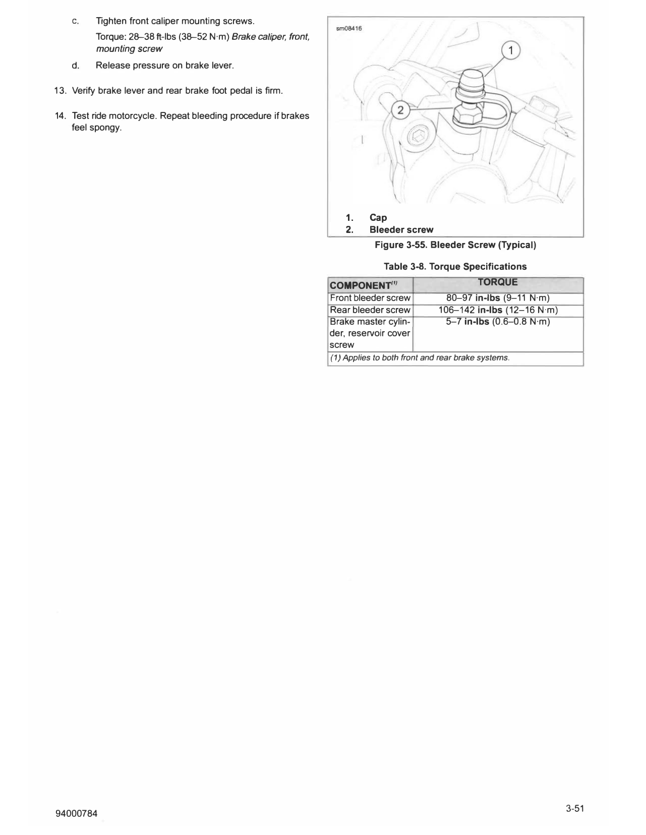
a. See Figure 3-55. Remove cap (1) from bleeder screw cylinder was replaced or master cylinder was ran dry during
(2). bleed procedure.
b. Attach vacuum brake bleeder to a caliper bleeder
12. Tighten procedure for front caliper mounting screws.
screw. Loosen screw 3/4 turn.
c. Operate vacuum bleeder to evacuate just the air a. Pump brake lever until firm.
from master cylinder and line.
b. Have a helper compress brake lever, hold in
d. Close bleeder screw. Tighten. Refer to Table 3-8. compressed position.
3-50 94000784
C. Tighten front caliper mounting screws.
Torque: 2�38 ft-lbs (3�52 N·m) Brake caliper, front,
mounting screw
d. Release pressure on brake lever.
1 3. Verify brake lever and rear brake foot pedal is firm.
14. Test ride motorcycle. Repeat bleeding procedure if brakes
feel spongy.
1. Cap
2. Bleeder screw
Figure 3-55. Bleeder Screw {Typical)
Table 3-8. Torque Specifications
COMPONENT''1 TORQUE
Front bleeder screw 80-97 in-lbs (9-11 N·m)
Rear bleeder screw 106-142 in-lbs (12-16 N·m)
Brake master cylin- 5-7 in-lbs (0.6-0.8 N·m)
der, reservoir cover
screw
( 1) Applies to both front and rear brake systems.