3.19 Abs Module
Fragment manuala — str. 124–126
📋 Tekst do skopiowania (OCR/wyszukiwanie)
ABS MODULE 3.19
GENERAL b. Remove ABS module (2) from mounting bracket (2).
NOTE INSTALL
The ABS module consists of the Hydraulic Control Unit (HCU)
and the Electronic Control Unit (ECU). The two are not serviced PART NUMBER TOOL NAME
separately. HD-48650 DIGITAL TECHNICIAN II
PREPARE FASTENER TORQUE VALUE
ABS module banjo bolts 17-19 ft-lbs 23-26 N·m
1. Remove main fuse. See POWER DISCONNECT ABS module bracket to frame 62-80 in-lbs 7-9 N·m
(Page 8-4). screws
ABS module frame cover 62-80 in-lbs 7-9 N·m
2. Remove seat. See SEAT (Page 3-113). screw
ABS module to mounting 40-58 in-lbs 4.5--6.5 N·m
3. Disconnect BCM. See BODY CONTROL MODULE (BCM) bracket screws
(Page 8-39).
NOTICE
4. Drain brake lines. See BLEED BRAKES (Page 3-49).
This device is sensitive to electrostatic discharge (ESD).
5. Remove screw from clamp securing both rear brake lines To prevent damage to the device, always touch the
to the ABS module mounting bracket. See BRAKE LINES motorcycle frame or a grounded surface before handling.
(Page 3-40). (00588c)
REMOVE 1. See Figure 3-53. Assemble ABS module to bracket.
NOTICE a. Install ABS module (1) to bracket (2) with screws (6),
washers (5), grommets (3) and compression limiters
This device is sensitive to electrostatic discharge (ESD). (4).
To prevent damage to the device, always touch the
motorcycle frame or a grounded surface before handling. b. Tighten screws.
(00588c) Torque: 40-58 in-lbs (4.5--6.5 N·m) ABS module to
mounting bracket screws
1. See Figure 3-52. Remove ABS module frame cover.
2. See Figure 3-51. Install ABS module and bracket
assembly.
a. Remove screw (1).
b. Remove frame cover (2). a. Install ABS module bracket (2).
b. Install screws (1). Tighten.
2. See Figure 3-50. Disconnect brake lines.
Torque: 62-80 in-lbs (7-9 N·m) ABS module bracket
a. Remove banjo bolts (1). to frame screws
b. 3. Attach wheel speed sensor connector (3).
Discard gasket washers (2).
c. Move brake lines (3-6) out of the way. 4. See Figure 3-50. Install brake lines.
d. Disconnect ABS connector (7). a. Place brake lines (3-6) in correct position.
3. See Figure 3-51. Remove ABS module and bracket b. Install each brake line with a banjo bolt (1) and new
assembly. gasket washers (2).
a. Detach WSS connector (3). c. Tighten banjo bolts.
Torque: 17-19 ft-lbs (23-26 N·m) ABS module banjo
b. Remove screws (1). bolts
c. Remove ABS module with ABS module bracket (2). 5. Connect ABS connector (7).
4. See Figure 3-53. Remove ABS module from bracket. 6. See Figure 3-52. Install ABS module frame cover.
a. Remove screws (6), washers (5), grommets (3) and a. Place frame cover (2) in position.
compression limiters (4).
3-46 94000784
b. Install screw (1 ). Tighten. ur
1424719
Torque: 62-80 in-lbs (7-9 N·m) ABS module frame
cover screw
7. If installing a new ABS module, use DTII for set-up
procedure:
Special Tool: DIGITAL TECHNICIAN II (HD-48650)
a. Choose REFLASH icon.
b. Follow on-screen prompts.
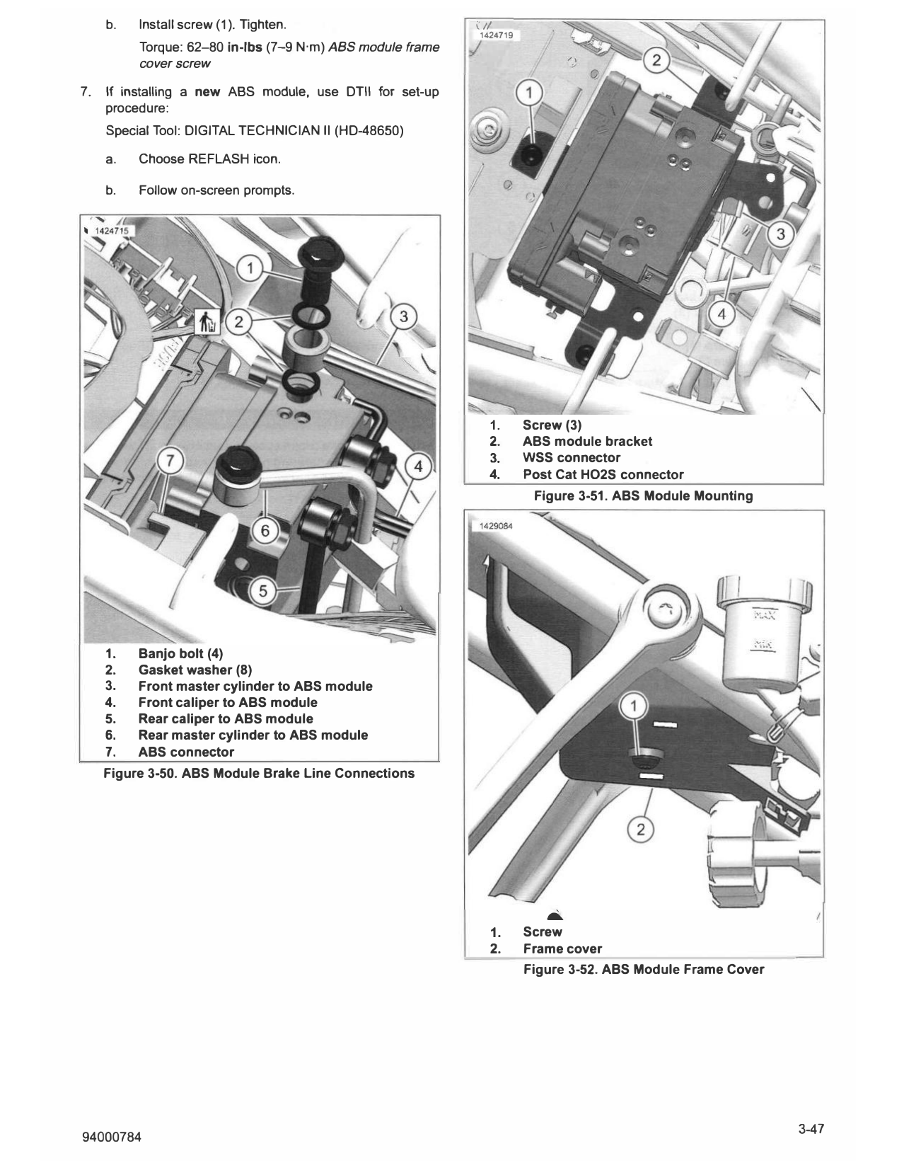
1. Screw (3)
2. ABS module bracket
3. WSS connector
4. Post Cat HO2S connector
Figure 3-51. ABS Module Mounting
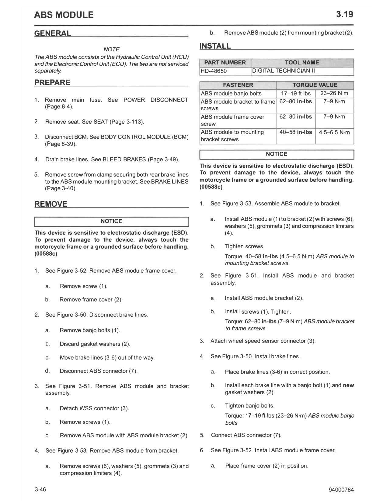
1. Banjo bolt (4)
2. Gasket washer (8)
3. Front master cylinder to ABS module
4. Front caliper to ABS module
5. Rear caliper to ABS module
6. Rear master cylinder to ABS module
7. ABS connector
Figure 3-50. ABS Module Brake Line Connections
1.
....
Screw
2. Frame cover
Figure 3-52. ABS Module Frame Cover
1429088 A WARNING
0--__ When any hydraulic brake component, line or connection
Is loosened or replaced on an ABS motorcycle, Digital
Technician II must be used during the brake bleeding
procedure to verify all air Is removed from the system.
--i -i�
Failure to properly bleed the brake system could adversely
affect braking, which could result In death or serious Injury.
(00585c)
�
1. Attach rear brake lines to ABS bracket. See BRAKE LINES
---® --
•• & (Page 3-40).
� 2. Connect BCM. See BODY CONTROL MODULE (BCM)
(Page 8-39).
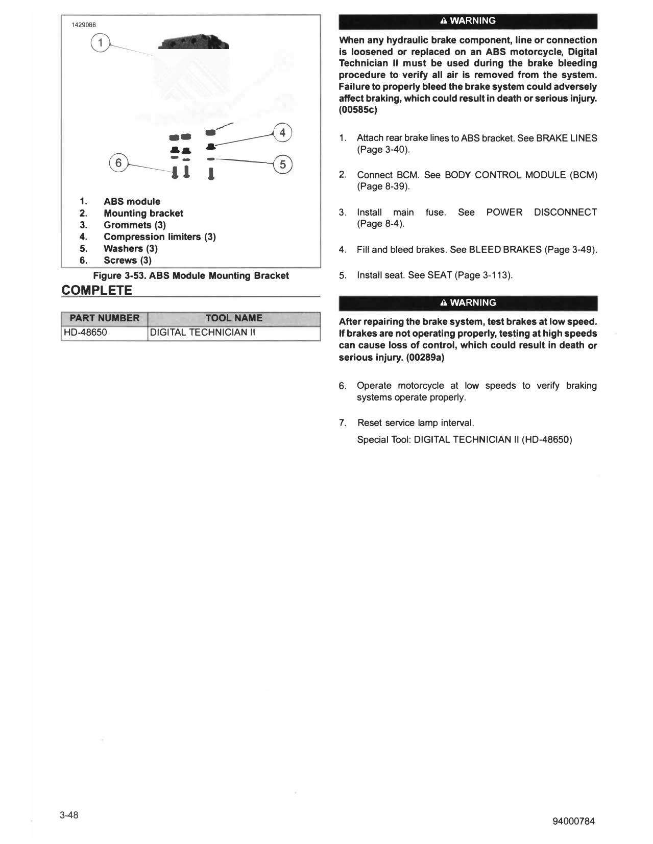
1. ABS module
2. Mounting bracket 3. Install main fuse. See POWER DISCONNECT
3. Grommets (3) (Page 8-4).
4. Compression limiters (3)
5. Washers (3) 4. Fill and bleed brakes. See BLEED BRAKES (Page 3-49).
6. Screws (3)
Figure 3-53. ABS Module Mounting Bracket 5. Install seat. See SEAT (Page 3-113).
COMPLETE
A WARNING
PART NUMBER TOOL NAME After repairing the brake system, test brakes at low speed.
HD-48650 DIGITAL TECHNICIAN II If brakes are not operating properly, testing at high speeds
can cause loss of control, which could result in death or
serious injury. (00289a)
6. Operate motorcycle at low speeds to verify braking
systems operate properly.
7. Reset service lamp interval.
Special Tool: DIGITAL TECHNICIAN II (HD-48650)