🏍️ PAN AMERICA SERWIS

3.18 Brake Lines

Fragment manuala — str. 118–123

📋 Tekst do skopiowania (OCR/wyszukiwanie)
BRAKE LINES                                                                                                        3.18

FRONT CROSSOVER BRAKE LINE

Prepare
1.   Drain front brake lines. See BLEED BRAKES (Page 3-49).

Remove
1.   Detach brake line from front brake calipers. See FRONT
     BRAKE CALIPER (Page 3-32).

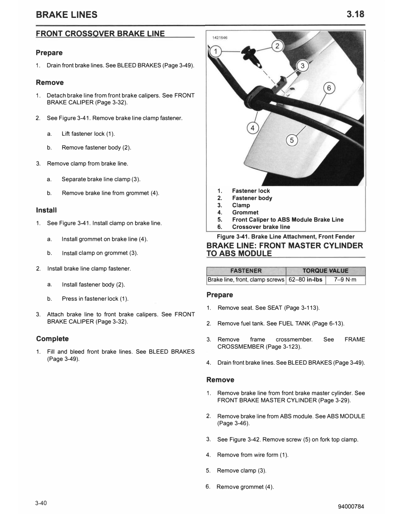
2.     See Figure 3-41. Remove brake line clamp fastener.

       a.   Lift fastener lock (1).

       b.   Remove fastener body (2).

3.     Remove clamp from brake line.

       a.   Separate brake line clamp (3).

       b.   Remove brake line from grommet (4).                    1.   Fastener lock
                                                                   2.   Fastener body
                                                                   3.   Clamp
Install                                                            4.   Grommet
                                                                   5.   Front Caliper to ABS Module Brake Line
1.     See Figure 3-41. Install clamp on brake line.
                                                                   6.   Crossover brake line

       a.   Install grommet on brake line (4).                     Figure 3-41. Brake Line Attachment, Front Fender
                                                              BRAKE LINE: FRONT MASTER CYLINDER
       b.   Install clamp on grommet (3).                     TO ABS MODULE
2.     Install brake line clamp fastener.                              FASTENER                   TORQUE VALUE
                                                              Brake line, front, clamp screws 62-80 in-lbs 7-9 N·m
       a.   Install fastener body (2).

       b.   Press in fastener lock (1).
                                                              Prepare
                                                              1.   Remove seat. See SEAT (Page 3-113).
3.     Attach brake line to front brake calipers. See FRONT
       BRAKE CALIPER (Page 3-32).                             2.   Remove fuel tank. See FUEL TANK (Page 6-13).

Complete                                                      3.   Remove  frame  crossmember.            See     FRAME
                                                                   CROSSMEMBER (Page 3-123).
1.     Fill and bleed front brake lines. See BLEED BRAKES
       (Page 3-49).
                                                              4.   Drain front brake lines. See BLEED BRAKES (Page 3-49).

                                                              Remove
                                                              1.   Remove brake line from front brake master cylinder. See
                                                                   FRONT BRAKE MASTER CYLINDER (Page 3-29).

                                                              2.   Remove brake line from ABS module. See ABS MODULE
                                                                   (Page 3-46).

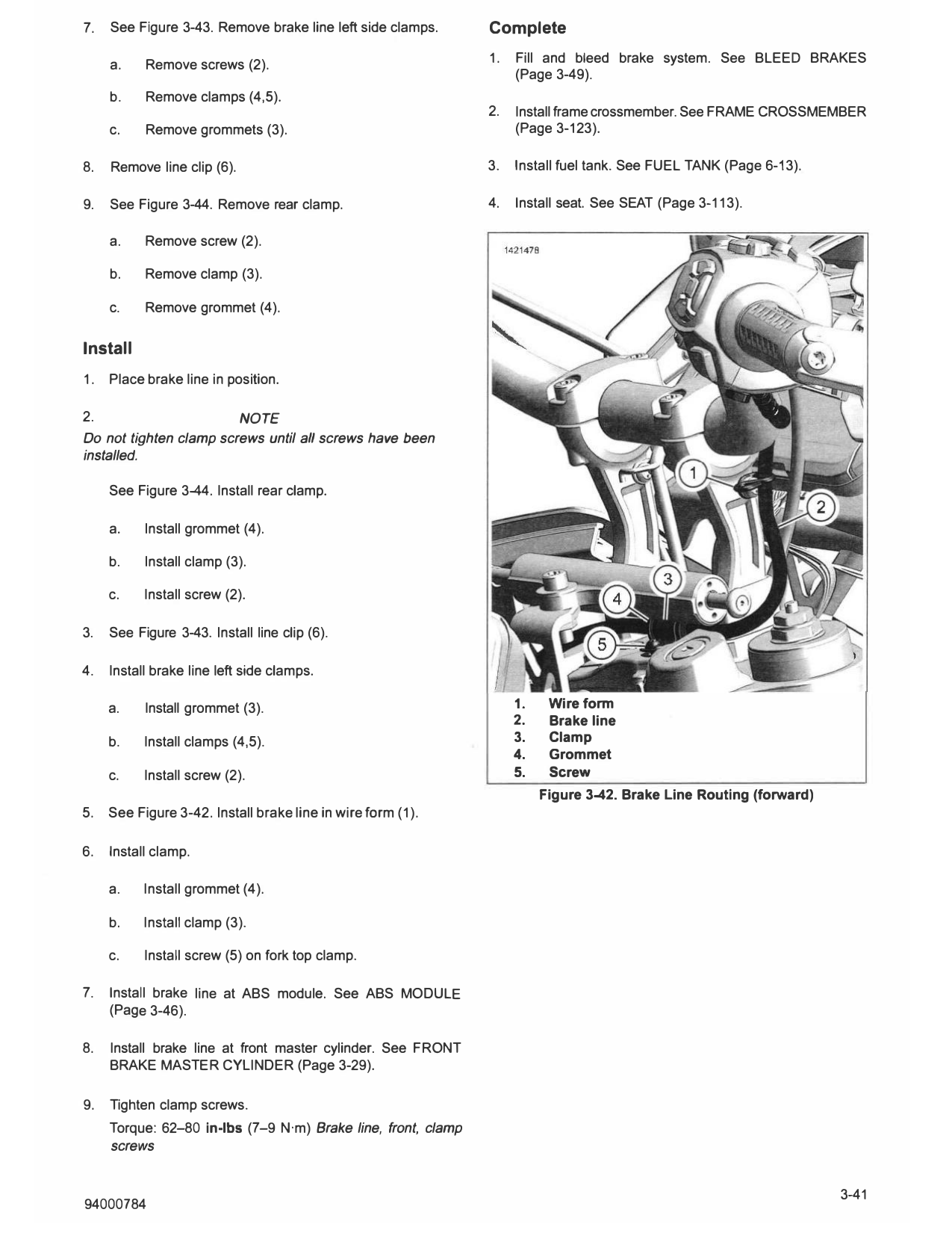
                                                              3.   See Figure 3-42. Remove screw (5) on fork top clamp.

                                                              4.   Remove from wire form (1).

                                                              5.   Remove clamp (3).

                                                              6.   Remove grommet (4).

7.   See Figure 3-43. Remove brake line left side clamps.      Complete

     a.    Remove screws (2).                                  1.   Fill and bleed brake system. See BLEED BRAKES
                                                                    (Page 3-49).
     b.    Remove clamps (4,5).
                                                               2.   Install frame crossmember. See FRAME CROSSMEMBER
     c.    Remove grommets (3).                                     (Page 3-123).

8.   Remove line clip (6).                                     3.   Install fuel tank. See FUEL TANK (Page 6-13).

9.   See Figure 3-44. Remove rear clamp.                       4.   Install seat. See SEAT (Page 3-113).

     a.    Remove screw (2).

     b.    Remove clamp (3).

     c.    Remove grommet (4).

Install
1.   Place brake line in position.

2.                           NOTE
Do not tighten clamp screws until all screws have been
installed.

     See Figure 3-44. Install rear clamp.

     a.    Install grommet (4).

     b.    Install clamp (3).

     c.    Install screw (2).

3.   See Figure 3-43. Install line clip (6).

4.   Install brake line left side clamps.

     a.    Install grommet (3).                                     1.    Wireform
                                                                    2.    Brake line
     b.    Install clamps (4,5).                                    3.    Clamp
                                                                    4.    Grommet
     c.    Install screw (2).                                       5.    Screw
                                                                         Figure 3-42. Brake Line Routing (forward)
5.   See Figure 3-42. Install brake line in wire form (1).

6.   Install clamp.

     a.    Install grommet (4).

     b.    Install clamp (3).

     c.    Install screw (5) on fork top clamp.

7.   Install brake line at ABS module. See ABS MODULE
     (Page 3-46).

8.   Install brake line at front master cylinder. See FRON T
     BRAKE MASTER CYLINDER (Page 3-29).

9.   Tighten clamp screws.
     Torque: 62-80 in-lbs (7-9 N·m) Brake line, front, clamp
     screws

                                                             4.   Drain front brake lines. See BLEED BRAKES (Page 3-49).

                                                             Remove
                                                             1.                        NOTE
                                                             Pan American has dual calipers with a crossover line
                                                             connecting them. Banjo fittings are stacked on right caliper.

                                                                  Remove front caliper to ABS module brake line from front
                                                                  brake caliper and fender. See Front Crossover Brake Line
                                                                  in this section.

                                                             2.   Remove brake line from ABS module. See ABS MODULE
                                                                  (Page 3-46).

                                                             3.   See Figure 3-45. Remove rear clamp.
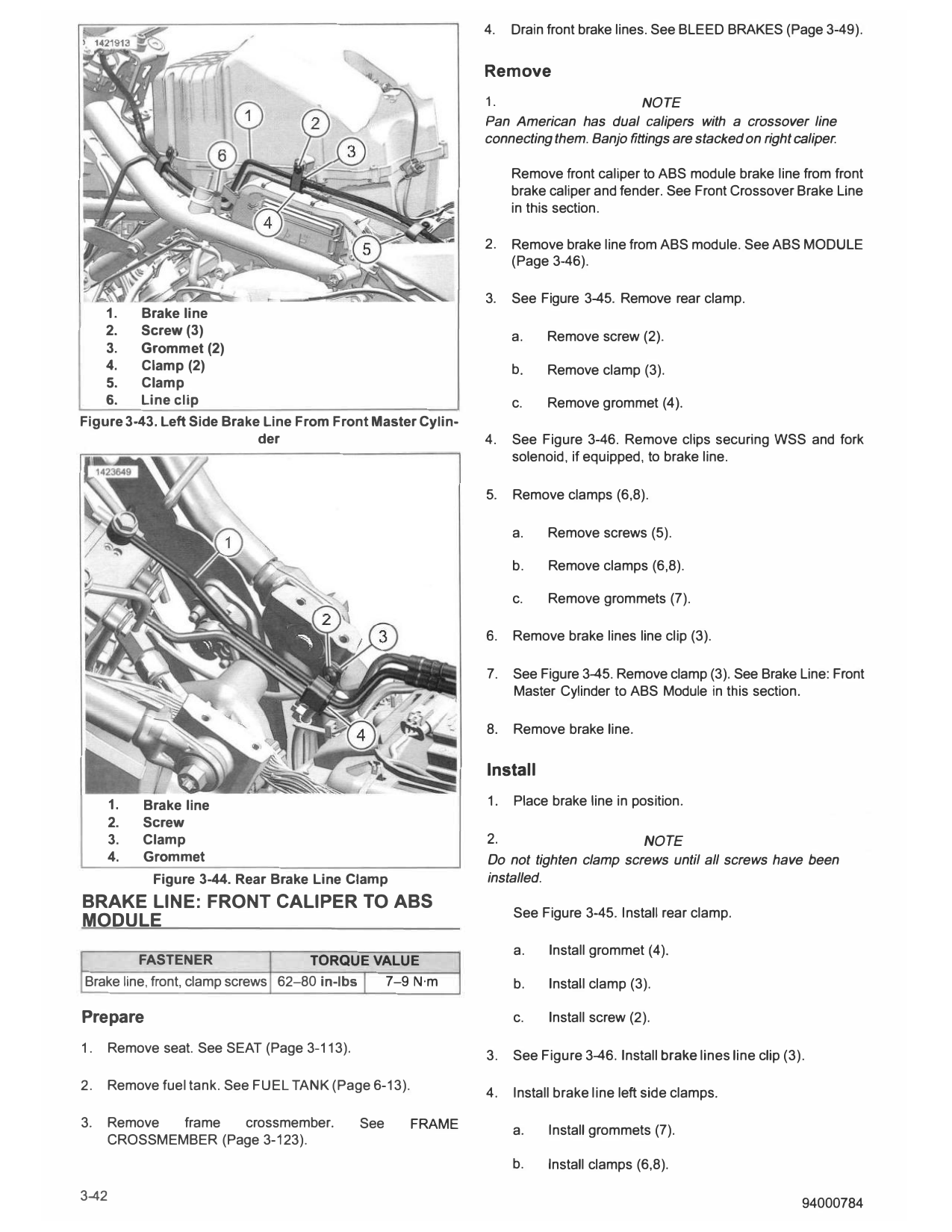
     1.   Brake line
     2.   Screw (3)                                               a.   Remove screw (2).
     3.   Grommet (2)
     4.   Clamp (2)                                               b.    Remove clamp (3).
     5.   Clamp
     6.   Line clip                                               c.   Remove grommet (4).
Figure 3-43. Left Side Brake Line From Front Master Cylin­
                            der                              4.   See Figure 3-46. Remove clips securing WSS and fork
                                                                  solenoid, if equipped, to brake line.

                                                             5.   Remove clamps (6,8).

                                                                  a.    Remove screws (5).

                                                                  b.    Remove clamps (6,8).

                                                                  c.    Remove grommets (7).

                                                             6.   Remove brake lines line clip (3).

                                                             7.   See Figure 3-45. Remove clamp (3). See Brake Line: Front
                                                                  Master Cylinder to ABS Module in this section.

                                                             8.   Remove brake line.

                                                             Install
     1.   Brake line                                         1.   Place brake line in position.
     2.   Screw
     3.   Clamp                                              2.                      NOTE
     4.   Grommet                                            Do not tighten clamp screws until all screws have been
           Figure 3-44. Rear Brake Line Clamp                installed.
BRAKE LINE: FRONT CALIPER TO ABS
                                                                  See Figure 3-45. Install rear clamp.
MODULE
                                                                  a.    Install grommet (4).
          FASTENER                  TORQUE VALUE
Brake line, front, clamp screws 62-80 in-lbs 7-9 N·m              b.    Install clamp (3).

Prepare                                                           c.    Install screw (2).

1.   Remove seat. See SEAT (Page 3-113).
                                                             3.   See Figure 3-46. Install brake lines line clip (3).

2.   Remove fuel tank. See FUEL TANK (Page 6-13).
                                                             4.   Install brake line left side clamps.

3.   Remove  frame  crossmember.           See      FRAME         a.    Install grommets (7).
     CROSSMEMBER (Page 3-123).
                                                                  b.    Install clamps (6,8).

3-42                                                                                                                94000784
     c.   Install screws (5).

5.   Install clips securing WSS and fork solenoid, if equipped,
     to brake line.

6.   Install brake line at ABS module. See ABS MODULE
     (Page 3-46).

7.   Install brake line at front caliper. See Front Crossover
     Brake Line in this section.

8.   Tighten clamp screws.
     Torque: 62-80 in-lbs (7-9 N·m) Brake line, front, clamp
     screws

Complete
1.   Fill and bleed brake system. See BLEED BRAKES
     (Page 3-49).

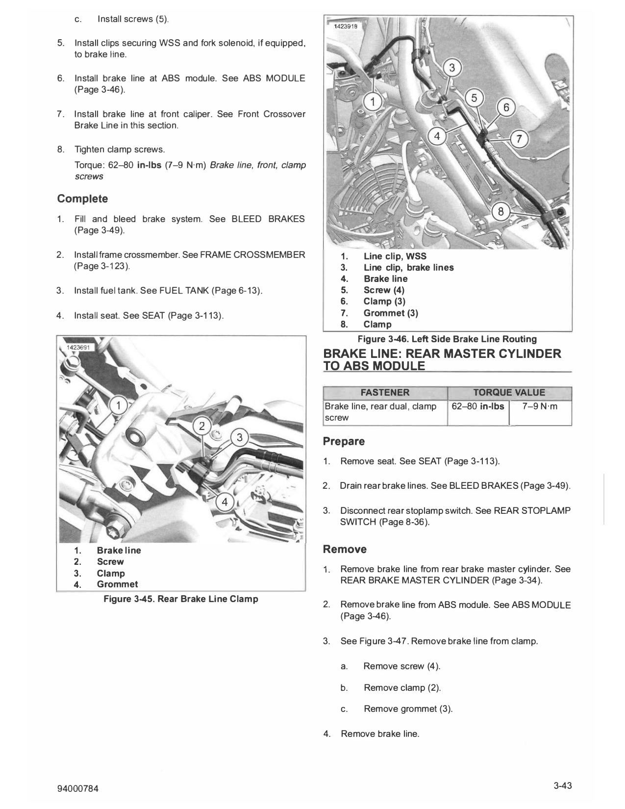
2.   Install frame crossmember. See FRAME CROSSMEMBER                  1.    Line clip, WSS
     (Page 3-123).                                                     3.    Line clip, brake lines
                                                                       4.    Brake line
3.   Install fuel tank. See FUEL TANK (Page 6-13).                     5.    Screw (4)
                                                                       6.    Clamp (3)
4.   Install seat. See SEAT (Page 3-113).                              7.    Grommet (3)
                                                                       8.    Clamp
                                                                            Figure 3-46. Left Side Brake Line Routing
                                                                  BRAKE LINE: REAR MASTER CYLINDER
                                                                  TO ABS MODULE

                                                                           FASTENER                   TORQUE VALUE
                                                                  Brake line, rear dual, clamp    62-80 in-lbs   7-9 N·m
                                                                                                               I
                                                                  screw

                                                                  Prepare
                                                                  1.   Remove seat. See SEAT (Page 3-113).

                                                                  2.   Drain rear brake lines. See BLEED BRAKES (Page 3-49).

                                                                  3.   Disconnect rear stoplamp switch. See REAR S TOPLAMP
                                                                       SWITCH (Page 8-36).

     1.   Brake line                                              Remove
     2.   Screw
     3.   Clamp                                                   1.   Remove brake line from rear brake master cylinder. See
     4.   Grommet                                                      REAR BRAKE MASTER CYLINDER (Page 3-34).

            Figure 3-45. Rear Brake Line Clamp
                                                                  2.   Remove brake line from ABS module. See ABS MODULE
                                                                       (Page 3-46).

                                                                  3.   See Figure 3-47. Remove brake line from clamp.

                                                                       a.    Remove screw (4).

                                                                       b.    Remove clamp (2).

                                                                       c.    Remove grommet (3).

                                                                  4.   Remove brake line.

94000784                                                                                                                 3-43
Install

                                                                                                                       I
                                                                               FASTENER                      TORQUE VALUE
                                                                      Brake line, rear fork, clamp       62-80 in-lbs 7-9 N·m
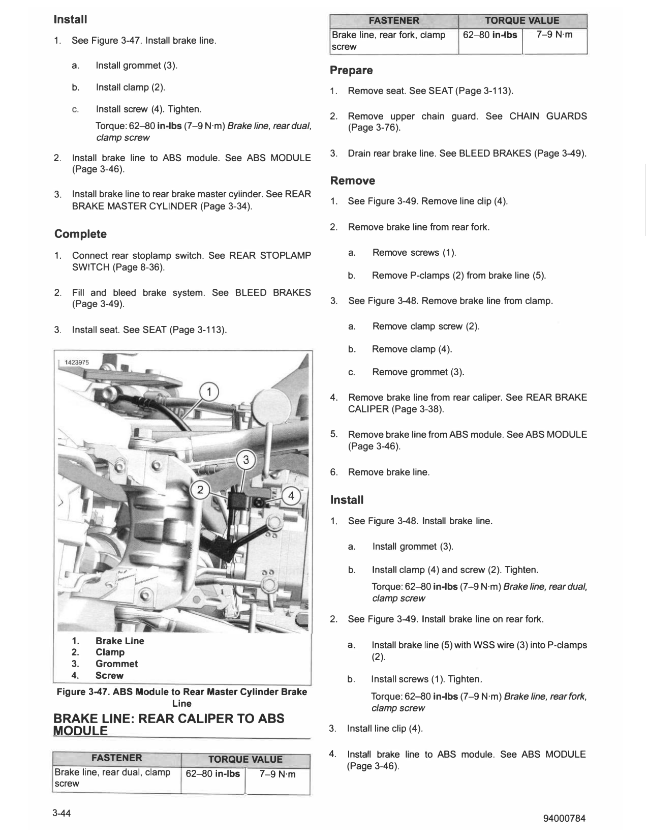
1.     See Figure 3-47. Install brake line.
                                                                      screw
       a.    Install grommet (3).
                                                                      Prepare
       b.    Install clamp (2).                                       1.   Remove seat. See SEAT (Page 3-113).
       c.    Install screw (4). Tighten.
                                                                      2.   Remove upper chain guard. See CHAIN GUARDS
             Torque: 62--80 in-lbs (7-9 N·m) Brake line, rear dual,        (Page 3-76).
             clamp screw

2.                                                                    3.   Drain rear brake line. See BLEED BRAKES (Page 3-49).
       Install brake line to ABS module. See ABS MODULE
       (Page 3-46).
                                                                      Remove
3.     Install brake line to rear brake master cylinder. See REAR
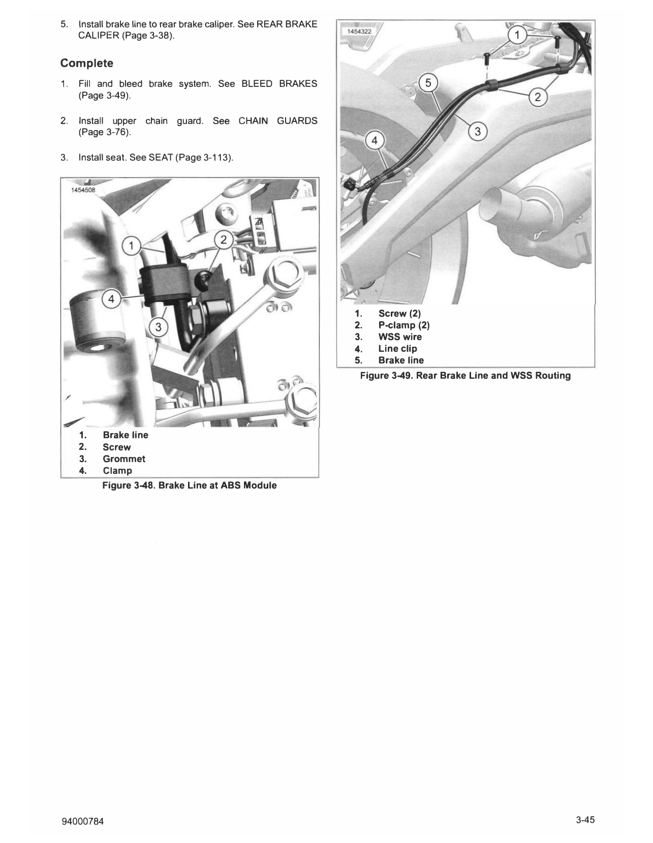
                                                                      1.   See Figure 3-49. Remove line clip (4).
       BRAKE MAS T ER CYLINDER (Page 3-34).

                                                                      2.   Remove brake line from rear fork.
Complete
1.     Connect rear stoplamp switch. See REAR ST OPLAMP                    a.     Remove screws (1).
       SWITCH (Page 8-36).
                                                                           b.     Remove P-clamps (2) from brake line (5).
2.     Fill and bleed brake system. See BLEED BRAKES
       (Page 3-49).                                                   3.   See Figure 3-48. Remove brake line from clamp.

3.     Install seat. See SEAT (Page 3-113).                                a.     Remove clamp screw (2).

                                                                           b.     Remove clamp (4).

                                                                           c.     Remove grommet (3).

                                                                      4.   Remove brake line from rear caliper. See REAR BRAKE
                                                                           CALIPER (Page 3-38).

                                                                      5.   Remove brake line from ABS module. See ABS MODULE
                                                                           (Page 3-46).

                                                                      6.   Remove brake line.

                                                                      Install
                                                                      1.   See Figure 3-48. Install brake line.

                                                                           a.     Install grommet (3).

                                                                           b.     Install clamp (4) and screw (2). Tighten.
                                                                                  Torque: 62--80 in-lbs (7-9 N·m) Brake line, rear dual,
                                                                                  clamp screw

                                                                      2.   See Figure 3-49. Install brake line on rear fork.

       1.   Brake Line                                                     a.     Install brake line (5) with WSS wire (3) into P-clamps
       2.   Clamp                                                                 (2).
       3.   Grommet
       4.   Screw                                                          b.     Install screws (1). Tighten.
 Figure 3-47. ABS Module to Rear Master Cylinder Brake                            Torque: 62--80 in-lbs (7-9 N·m) Brake line, rear fork,
                         Line                                                     clamp screw
BRAKE LINE: REAR CALIPER TO ABS
MODULE                                                                3.   Install line clip (4).

screw
         FASTENER
Brake line, rear dual, clamp                      I
                                        TORQUE VALUE
                                    62-80 in-lbs 7-9 N·m
                                                                      4.   Install brake line to ABS module. See ABS MODULE
                                                                           (Page 3-46).

5.   Install brake line to rear brake caliper. See REAR BRAKE
     CALIPER (Page 3-38).

Complete
1.   Fill and bleed brake system. See BLEED BRAKES
     (Page 3-49).

2.   Install upper chain guard. See CHAIN GUARDS
     (Page 3-76).

3.   Install seat. See SEAT (Page 3-113).

                                                                1.   Screw (2)
                                                                2.   P-clamp (2)
                                                                3.   WSS wire
                                                                4.   Line clip
                                                                5.   Brake line
                                                                 Figure 3-49. Rear Brake Line and WSS Routing

     1.   Brake line
     2.   Screw
     3.   Grommet
     4.   Clamp
          Figure 3-48. Brake Line at ABS Module

94000784                                                                                                        3-45