3.11 Tires
Fragment manuala — str. 101–104
📋 Tekst do skopiowania (OCR/wyszukiwanie)
TIRES 3.11
GENERAL NOTE
ABS models must use properly inflated tires and wheels that
A WARNING are the same as the original equipment. The ABS monitors
rotational speed of the wheels through individual wheel speed
Be sure tires are properly inflated, balanced, undamaged, sensors to determine the application of ABS.
and have adequate tread. Inspect your tires regularly and
see a Harley-Davidson dealer for replacements. Riding Different diameter wheels or tires can:
with excessively worn, unbalanced, improperly inflated,
• Alter the rotational speed which can upset the calibration of
overloaded or damaged tires can lead to tire failure and
the ABS.
adversely affect stability and handling, which could result
in death or serious injury. (00014b) • Adversely affect its ability to detect and prevent lockups.
Operating with over- or under-inflated tires can reduce ABS
Always maintain proper tire pressure. See INSPECT TIRES performance.
AND WHEELS (Page 2-9). Do not load tires beyond GAWR.
Refer to tables in SPECIFICATIONS (Page 3-5). PREPARE
Underinflated, over-inflated or overloaded tires can fail.
NOTE 1. Remove wheel. See FRONT WHEEL (Page 3-8) or REAR
• Check runout on wheel before installing a new tire. See WHEEL (Page 3-11).
CHECKING AND TRUING WHEELS (Page 3-16). 2. Check wheels for lateral and radial runout. See Checking
Wheel Runout (Page 3-16).
• Store new tires on a horizontal tire rack. Storing in a vertical
stack compresses the tires and closes the beads. REMOVE
• Inspect tires for punctures, cuts, breaks and wear at least
weekly. NOTE
• Wheels equipped with tire pressure sensors require special
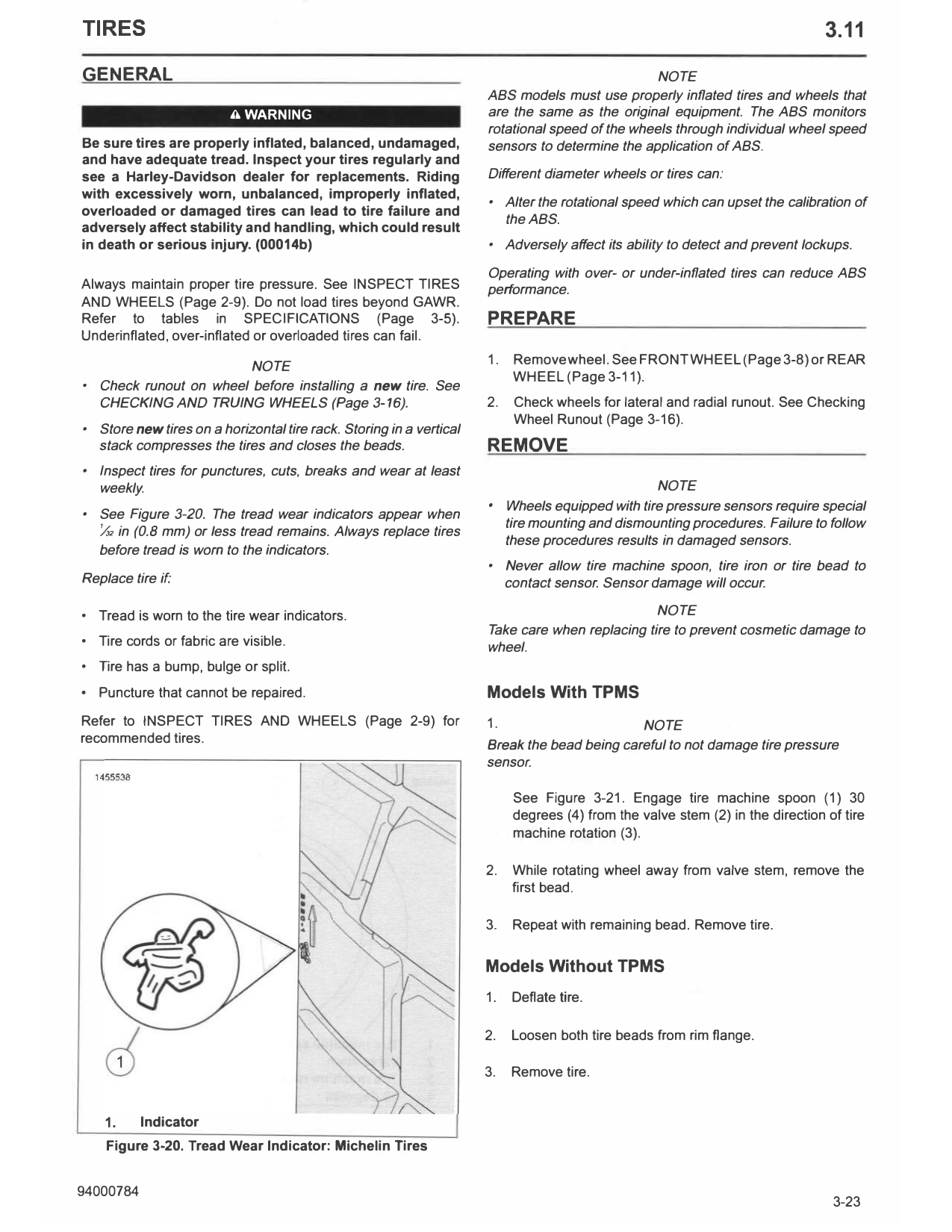
• See Figure 3-20. The tread wear indicators appear when
tire mounting and dismounting procedures. Failure to follow
¼ in (0.8 mm) or less tread remains. Always replace tires
these procedures results in damaged sensors.
before tread is worn to the indicators.
• Never allow tire machine spoon, tire iron or tire bead to
Replace tire if: contact sensor. Sensor damage will occur.
• Tread is worn to the tire wear indicators. NOTE
Take care when replacing tire to prevent cosmetic damage to
• Tire cords or fabric are visible. wheel.
• Tire has a bump, bulge or split.
• Puncture that cannot be repaired. Models With TPMS
Refer to INSPECT TIRES AND WHEELS (Page 2-9) for 1. NOTE
recommended tires. Break the bead being careful to not damage tire pressure
sensor.
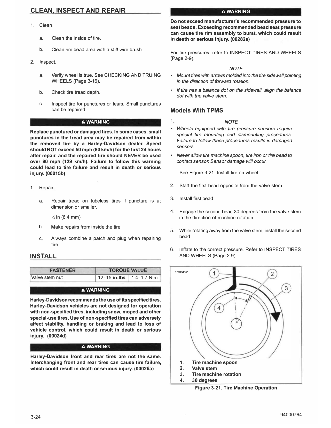
See Figure 3-21. Engage tire machine spoon (1) 30
degrees (4) from the valve stem (2) in the direction of tire
machine rotation (3).
2. While rotating wheel away from valve stem, remove the
first bead.
3. Repeat with remaining bead. Remove tire.
Models Without TPMS
1. Deflate tire.
2. Loosen both tire beads from rim flange.
3. Remove tire.
1. Indicator
Figure 3-20. Tread Wear Indicator: Michelin Tires
CLEAN, INSPECT AND REPAIR A WARNING
Do not exceed manufacturer's recommended pressure to
1. Clean. seat beads. Exceeding recommended bead seat pressure
can cause tire rim assembly to burst, which could result
a. Clean the inside of tire. in death or serious injury. (00282a)
b. Clean rim bead area with a stiff wire brush.
For tire pressures, refer to INSPECT TIRES AND WHEELS
(Page 2-9).
2. Inspect.
NOTE
a. Verify wheel is true. See CHECKING AND TRUING • Mount tires with arrows molded into the tire sidewall pointing
WHEELS (Page 3-16). in the direction offorward rotation.
b. Check tire tread depth. • If tire has a balance dot on the sidewall, align the balance
dot with the valve stem.
c. Inspect tire for punctures or tears. Small punctures
can be repaired. Models With TPMS
A WARNING 1. NOTE
• Wheels equipped with tire pressure sensors require
Replace punctured or damaged tires. In some cases, small
special tire mounting and dismounting procedures.
punctures in the tread area may be repaired from within
Failure to follow these procedures results in damaged
the removed tire by a Harley-Davidson dealer. Speed
sensors.
should NOT exceed 50 mph (80 km/h) for the first 24 hours
after repair, and the repaired tire should NEVER be used • Never allow tire machine spoon, tire iron or tire bead to
over 80 mph (129 km/h). Failure to follow this warning contact sensor. Sensor damage will occur.
could lead to tire failure and result in death or serious
injury. (00015b) See Figure 3-21. Install tire on wheel.
1. Repair. 2. Start the first bead opposite from the valve stem.
3. Install first bead.
a. Repair tread on tubeless tires if puncture is at
dimension or smaller.
4. Engage the second bead 30 degrees from the valve stem
¼ in (6.4 mm) in the direction of machine rotation.
b. Make repairs from inside the tire.
5. While rotating away from the valve stem, install the second
c. Always combine a patch and plug when repairing bead.
tire.
6. Inflate to the correct pressure. Refer to INSPECT TIRES
INSTALL AND WHEELS (Page 2-9).
FASTENER TORQUE VALUE sm08492
Valve stem nut 12-15 in-lbs 1.4-1.7 N·m
A WARNING
Harley-Davidson recommends the use of its specified tires.
Harley-Davidson vehicles are not designed for operation
with non-specified tires, including snow, moped and other
special-use tires. Use of non-specified tires can adversely
affect stability, handling or braking and lead to loss of
vehicle control, which could result in death or serious
injury. (00024d)
A WARNING
Harley-Davidson front and rear tires are not the same.
Interchanging front and rear tires can cause tire failure, 1. Tire machine spoon
which could result in death or serious injury. (00026a) 2. Valve stem
3. Tire machine rotation
4. 30 degrees
Figure 3-21. Tire Machine Operation
3-24 94000784
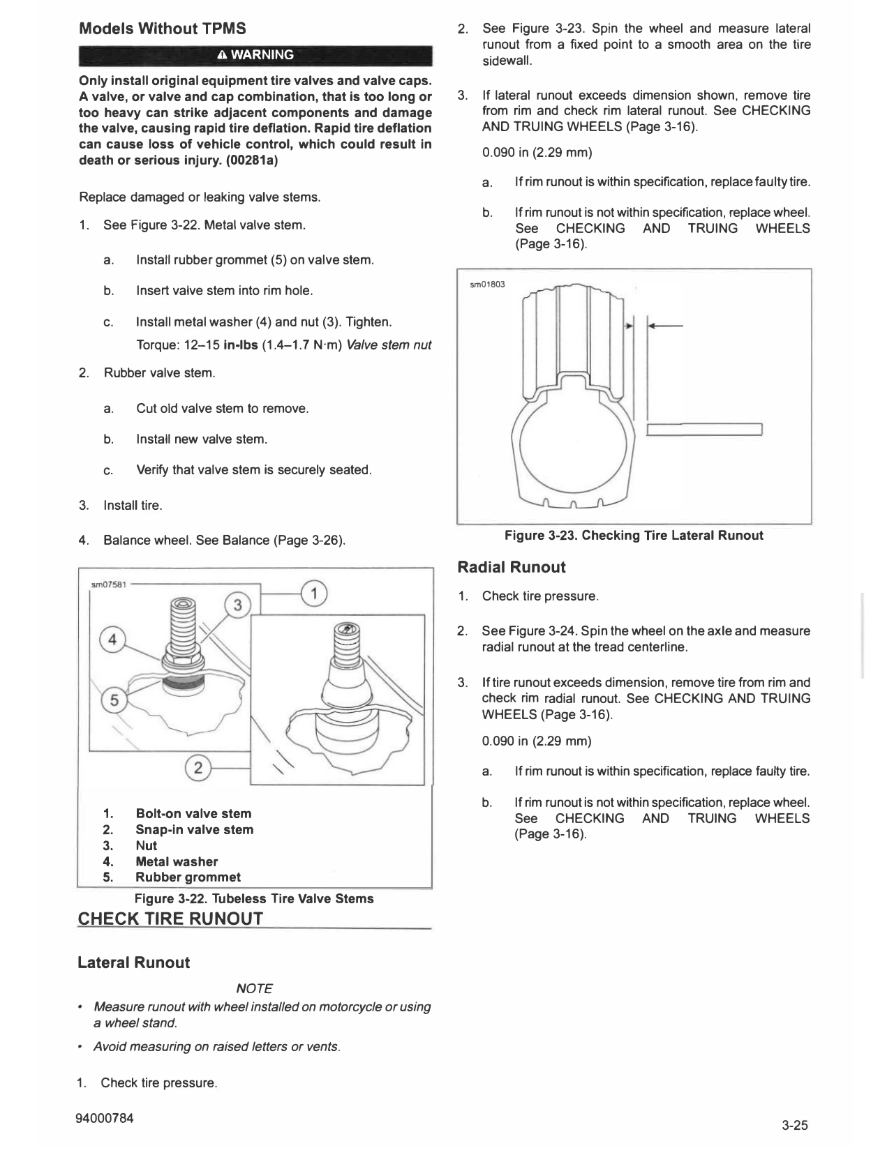
Models Without TPMS 2. See Figure 3-23. Spin the wheel and measure lateral
runout from a fixed point to a smooth area on the tire
A WARNING sidewall.
Only install original equipment tire valves and valve caps.
A valve, or valve and cap combination, that is too long or 3. If lateral runout exceeds dimension shown, remove tire
too heavy can strike adjacent components and damage from rim and check rim lateral runout. See CHECKING
the valve, causing rapid tire deflation. Rapid tire deflation AND TRUING WHEELS (Page 3-16).
can cause loss of vehicle control, which could result in
0.090 in (2.29 mm)
death or serious injury. (00281a)
a. If rim runout is within specification, replace faulty tire.
Replace damaged or leaking valve stems.
b. If rim runout is not within specification, replace wheel.
1. See Figure 3-22. Metal valve stem. See CHECKING AND T RUING WHEELS
(Page 3-16).
a. Install rubber grommet (5) on valve stem.
sm01803
b. Insert valve stem into rim hole.
c. Install metal washer (4) and nut (3). Tighten.
Torque: 12-15 in-lbs (1.4-1.7 N·m) Valve stem nut
2. Rubber valve stem.
a. Cut old valve stem to remove.
b. Install new valve stem.
c. Verify that valve stem is securely seated.
3. Install tire.
4. Balance wheel. See Balance (Page 3-26). Figure 3-23. Checking Tire Lateral Runout
Radial Runout
1. Check tire pressure.
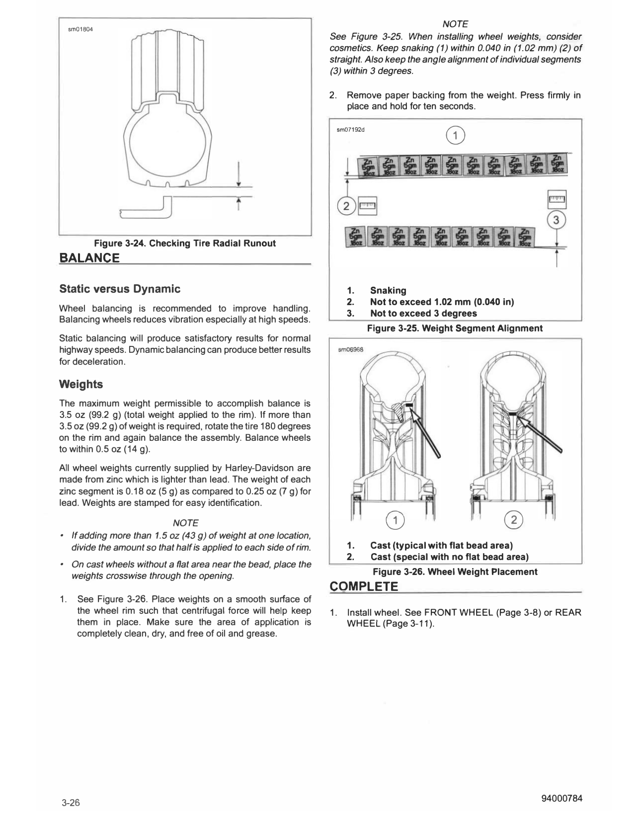
2. See Figure 3-24. Spin the wheel on the axle and measure
radial runout at the tread centerline.
3. lf tire runout exceeds dimension, remove tire from rim and
check rim radial runout. See CHECKING AND TRUING
WHEELS (Page 3-16).
0.090 in (2.29 mm)
a. If rim runout is within specification, replace faulty tire.
b. If rim runout is not within specification, replace wheel.
1. Bolt-on valve stem See CHECKING AND TRUING WHEELS
2. Snap-in valve stem (Page 3-16).
3. Nut
4. Metal washer
5. Rubber grommet
Figure 3-22. Tubeless Tire Valve Stems
CHECK TIRE RUNOUT
Lateral Runout
NOTE
• Measure runout with wheel installed on motorcycle or using
a wheel stand.
• Avoid measuring on raised letters or vents.
1. Check tire pressure.
sm01804
NOTE
See Figure 3-25. When installing wheel weights, consider
cosmetics. Keep snaking (1) within 0.040 in (1.02 mm) (2) of
straight. Also keep the angle alignment of individual segments
(3) within 3 degrees.
2. Remove paper backing from the weight. Press firmly in
place and hold for ten seconds.
sm07192d
0
Figure 3-24. Checking Tire Radial Runout
BALANCE
Static versus Dynamic 1. Snaking
2. Not to exceed 1.02 mm (0.040 in)
Wheel balancing is recommended to improve handling.
3. Not to exceed 3 degrees
Balancing wheels reduces vibration especially at high speeds.
Figure 3-25. Weight Segment Alignment
Static balancing will produce satisfactory results for normal
highway speeds. Dynamic balancing can produce better results
for deceleration.
Weights
The maximum weight permissible to accomplish balance is
3.5 oz (99.2 g) (total weight applied to the rim). If more than
3.5 oz (99.2 g) of weight is required, rotate the tire 180 degrees
on the rim and again balance the assembly. Balance wheels
to within 0.5 oz (14 g).
All wheel weights currently supplied by Harley-Davidson are
made from zinc which is lighter than lead. The weight of each
zinc segment is 0.18 oz (5 g) as compared to 0.25 oz (7 g) for
lead. Weights are stamped for easy identification.
NOTE
• If adding more than 1.5 oz (43 g) of weight at one location,
0 0
divide the amount so that half is applied to each side of rim. 1. Cast (typical with flat bead area)
2. Cast (special with no flat bead area)
• On cast wheels without a flat area near the bead, place the
weights crosswise through the opening. Figure 3-26. Wheel Weight Placement
COMPLETE
1. See Figure 3-26. Place weights on a smooth surface of
the wheel rim such that centrifugal force will help keep 1. Install wheel. See FRONT WHEEL (Page 3-8) or REAR
them in place. Make sure the area of application is WHEEL (Page 3-11).
completely clean, dry, and free of oil and grease.
3-26 94000784