2.18 Adjust Suspension
Fragment manuala — str. 61–65
📋 Tekst do skopiowania (OCR/wyszukiwanie)
ADJUST SUSPENSION 2.18
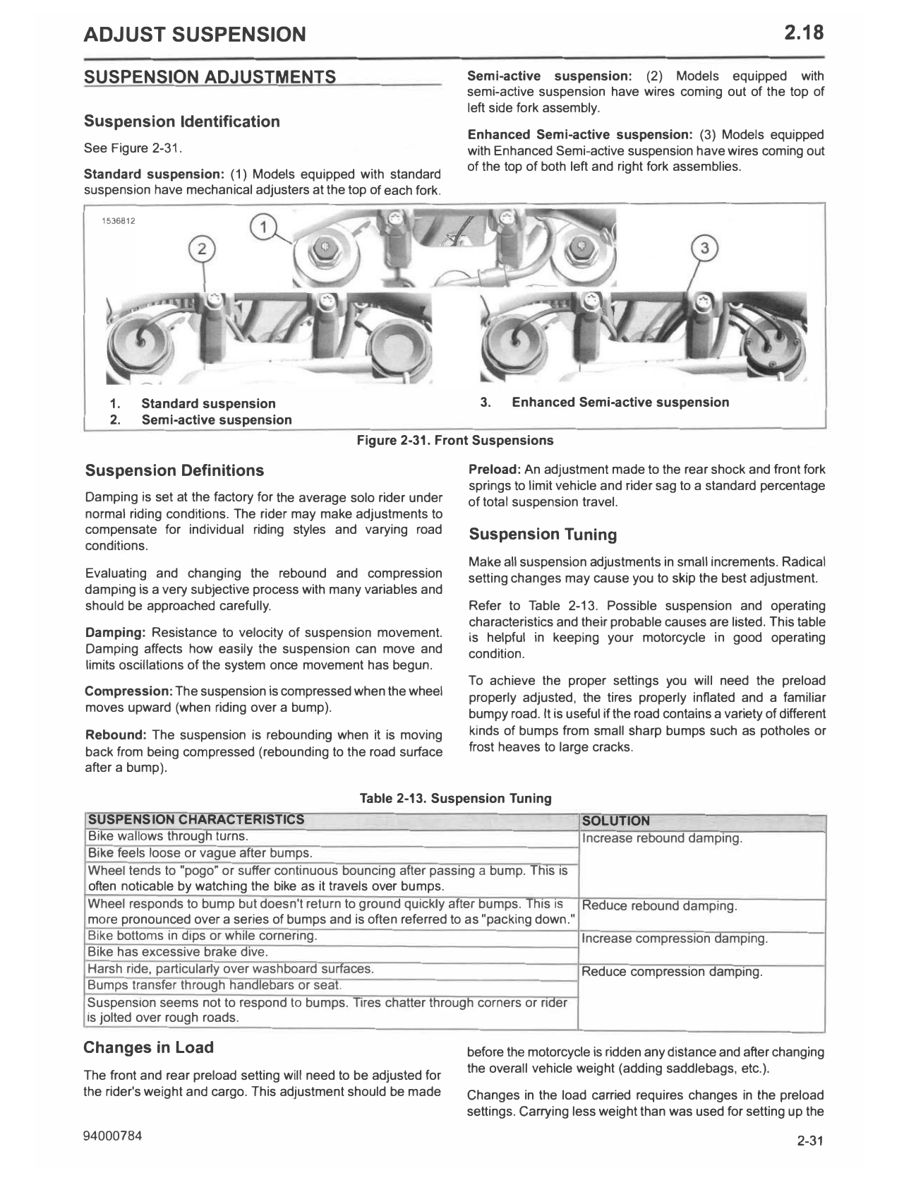
SUSPENSION ADJUSTMENTS Semi-active suspension: (2) Models equipped with
semi-active suspension have wires coming out of the top of
left side fork assembly.
Suspension Identification
Enhanced Semi-active suspension: (3) Models equipped
See Figure 2-31. with Enhanced Semi-active suspension have wires coming out
of the top of both left and right fork assemblies.
Standard suspension: (1) Models equipped with standard
suspension have mechanical adjusters at the top of each fork.
1536812
1. Standard suspension 3. Enhanced Semi-active suspension
2. Semi-active suspension
Figure 2-31. Front Suspensions
Suspension Definitions Preload: An adjustment made to the rear shock and front fork
springs to limit vehicle and rider sag to a standard percentage
Damping is set at the factory for the average solo rider under of total suspension travel.
normal riding conditions. The rider may make adjustments to
compensate for individual riding styles and varying road Suspension Tuning
conditions.
Make all suspension adjustments in small increments. Radical
Evaluating and changing the rebound and compression setting changes may cause you to skip the best adjustment.
damping is a very subjective process with many variables and
should be approached carefully. Refer to Table 2-13. Possible suspension and operating
characteristics and their probable causes are listed. This table
Damping: Resistance to velocity of suspension movement. is helpful in keeping your motorcycle in good operating
Damping affects how easily the suspension can move and condition.
limits oscillations of the system once movement has begun.
To achieve the proper settings you will need the preload
Compression: The suspension is compressed when the wheel properly adjusted, the tires properly inflated and a familiar
moves upward (when riding over a bump). bumpy road. It is useful if the road contains a variety of different
Rebound: The suspension is rebounding when it is moving kinds of bumps from small sharp bumps such as potholes or
back from being compressed (rebounding to the road surface frost heaves to large cracks.
after a bump).
Table 2-13. Suspension Tuning
SUSPENSION CHARACTERISTICS SOLUTION
Bike wallows through turns. Increase rebound damping.
Bike feels loose or vague after bumps.
Wheel tends to "pogo" or suffer continuous bouncing after passing a bump. This is
often noticable by watching the bike as it travels over bumps.
Wheel responds to bump but doesn't return to ground quickly after bumps. This is Reduce rebound damping.
more pronounced over a series of bumps and is often referred to as "packing down."
Bike bottoms in dips or while cornering. Increase compression damping.
Bike has excessive brake dive.
Harsh ride, particularly over washboard surfaces. Reduce compression damping.
Bumps transfer through handlebars or seat.
Suspension seems not to respond to bumps. Tires chatter through corners or rider
is jolted over rough roads.
Changes in Load before the motorcycle is ridden any distance and after changing
the overall vehicle weight (adding saddlebags, etc.).
The front and rear preload setting will need to be adjusted for
the rider's weight and cargo. This adjustment should be made Changes in the load carried requires changes in the preload
settings. Carrying less weight than was used for setting up the
94000784 2-31
suspension requires decreasing the amount of preload.
Increasing the load carried requires adding more preload.
ELECTRONIC SUSPENSION
For manual suspension adjustment Refer to Manual
Suspension (Page 2-33).
Enhanced Semi-active Suspension
Models equipped with enhanced semi-active suspension have
wires coming out of the top of both left and right fork
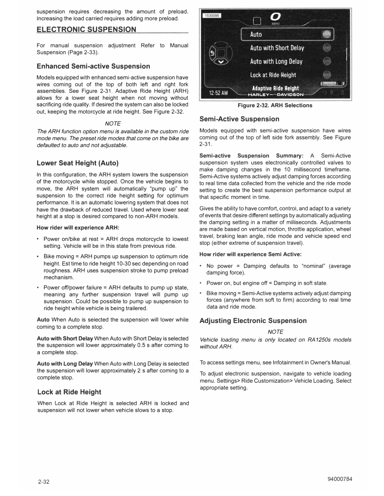
assemblies. See Figure 2-31. Adaptive Ride Height (ARH)
allows for a lower seat height when not moving without
sacrificing ride quality. If desired the system can also be locked Figure 2-32. ARH Selections
out, keeping the motorcycle at ride height. See Figure 2-32.
Semi-Active Suspension
NOTE
The ARH function option menu is available in the custom ride Models equipped with semi-active suspension have wires
mode menu. The preset ride modes that come on the bike are coming out of the top of left side fork assembly. See Figure
defaulted to auto and not adjustable. 2-31.
Semi-active Suspension Summary: A Semi-Active
Lower Seat Height (Auto) suspension system uses electronically controlled valves to
make damping changes in the 10 millisecond timeframe.
In this configuration, the ARH system lowers the suspension Semi-Active systems actively adjust damping forces according
of the motorcycle while stopped. Once the vehicle begins to to real time data collected from the vehicle and the ride mode
move, the ARH system will automatically "pump up" the setting to create the best suspension performance output at
suspension to the correct ride height setting for optimum that specific moment in time.
performance. It is an automatic lowering system that does not
have the drawback of reduced travel. Used where lower seat Gives the ability to have comfort, control, and adapt to a variety
height at a stop is desired compared to non-ARH models. of events that desire different settings by automatically adjusting
the damping setting in a matter of milliseconds. Adjustments
How rider will experience ARH: are made based on vertical motion, throttle application, wheel
• Power on/bike at rest = ARH drops motorcycle to lowest travel, braking lean angle, ride mode and vehicle speed end
stop (either extreme of suspension travel).
setting. Vehicle will be in this state from previous ride.
• Bike moving= ARH pumps up suspension to optimum ride How rider will experience Semi Active:
height. Est time to ride height 10-30 sec depending on road • No power = Damping defaults to "nominal" (average
roughness. ARH uses suspension stroke to pump preload damping force).
mechanism.
• Power on, but engine off= Damping in soft state.
• Power off/power failure= ARH defaults to pump up state,
meaning any further suspension travel will pump up • Bike moving= Semi-Active systems actively adjust damping
suspension. Could be possible to pump up suspension to forces (anywhere from soft to firm) according to real time
ride height while vehicle is being trailered. data and ride mode.
Auto When Auto is selected the suspension will lower while Adjusting Electronic Suspension
coming to a complete stop.
NOTE
Auto with Short Delay When Auto with Short Delay is selected Vehicle loading menu is only located on RA 1250s models
the suspension will lower approximately 0.5 s after coming to without ARH.
a complete stop.
Auto with Long Delay When Auto with Long Delay is selected To access settings menu, see Infotainment in Owner's Manual.
the suspension will lower approximately 2 s after coming to a
To adjust electronic suspension, navigate to vehicle loading
complete stop.
menu. Settings> Ride Customization> Vehicle Loading. Select
appropriate setting.
Lock at Ride Height
When Lock at Ride Height is selected ARH is locked and
suspension will not lower when vehicle slows to a stop.
2-32 94000784
2. Turn compression adjuster counter-clockwise in the S
(soft) direction the recommended number of turns. Refer
to Table 2-16.
Preload Adjustment
1. See Figure 2-36. Rotate the preload adjuster knob
clockwise in the HIGH direction to increase preload setting,
or counterclockwise to decrease preload setting until
desired setting is reached.
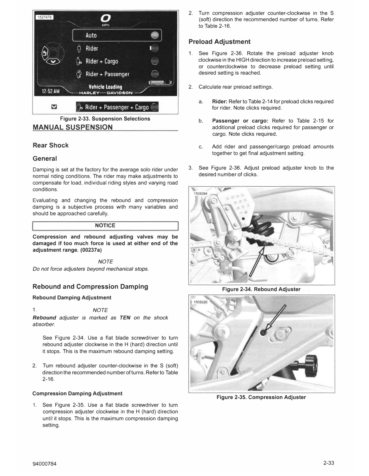
2. Calculate rear preload settings.
a. Rider: Refer to Table 2-14 for preload clicks required
• jb Rider+ Passenger+ Cargo for rider. Note clicks required.
Figure 2-33. Suspension Selections b. Passenger or cargo: Refer to Table 2-15 for
MANUAL SUSPENSION additional preload clicks required for passenger or
cargo. Note clicks required.
Rear Shock c. Add rider and passenger/cargo preload amounts
together to get final adjustment setting.
General
Damping is set at the factory for the average solo rider under 3. See Figure 2-36. Adjust preload adjuster knob to the
normal riding conditions. The rider may make adjustments to desired number of clicks.
compensate for load, individual riding styles and varying road
conditions.
Evaluating and changing the rebound and compression
damping is a subjective process with many variables and
should be approached carefully.
NOTICE
Compression and rebound adjusting valves may be
damaged if too much force is used at either end of the
adjustment range. (00237a)
NOTE
Do not force adjusters beyond mechanical stops.
Rebound and Compression Damping Figure 2-34. Rebound Adjuster
Rebound Damping Adjustment
1. NOTE
Rebound adjuster is marked as TEN on the shock
absorber.
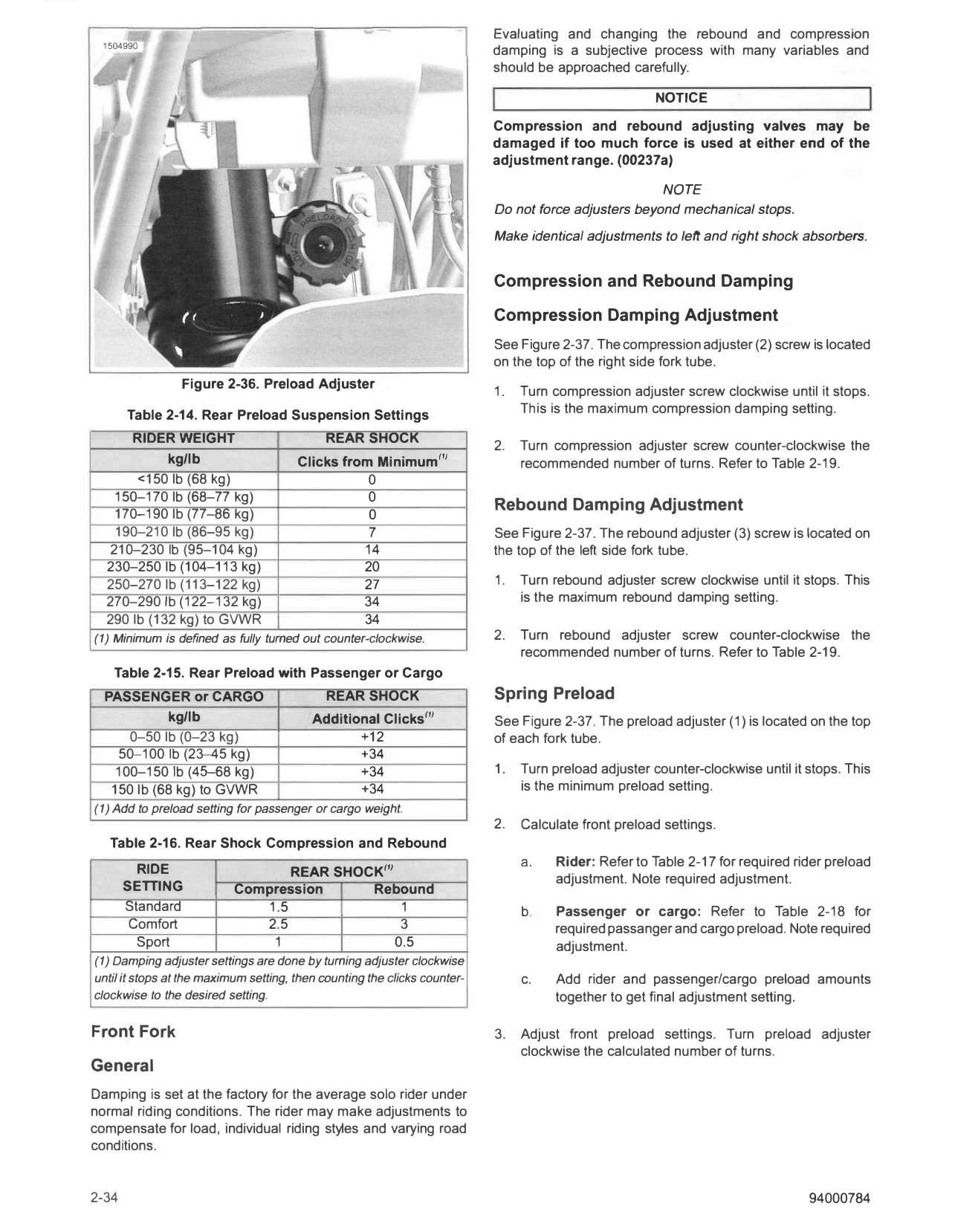
See Figure 2-34. Use a flat blade screwdriver to turn
rebound adjuster clockwise in the H (hard) direction until
it stops. This is the maximum rebound damping setting.
2. Turn rebound adjuster counter-clockwise in the S (soft)
direction the recommended number of turns. Refer to Table
2-16.
Compression Damping Adjustment
Figure 2-35. Compression Adjuster
1. See Figure 2-35. Use a flat blade screwdriver to turn
compression adjuster clockwise in the H (hard) direction
until it stops. This is the maximum compression damping
setting.
94000784 2-33
Evaluating and changing the rebound and compression
1504990
damping is a subjective process with many variables and
should be approached carefully.
NOTICE
Compression and rebound adjusting valves may be
damaged if too much force is used at either end of the
adjustment range. (00237a)
NOTE
Do not force adjusters beyond mechanical stops.
Make identical adjustments to left and right shock absorbers.
Compression and Rebound Damping
Compression Damping Adjustment
See Figure 2-37. The compression adjuster (2) screw is located
on the top of the right side fork tube.
Figure 2-36. Preload Adjuster
1. Turn compression adjuster screw clockwise until it stops.
Table 2-14. Rear Preload Suspension Settings This is the maximum compression damping setting.
RIDER WEIGHT REAR SHOCK
2. Turn compression adjuster screw counter-clockwise the
kg/lb Clicks from Minimum 1'1 recommended number of turns. Refer to Table 2-19.
<150 lb (68 kg) 0
150-170 lb (68-77 kg) 0
Rebound Damping Adjustment
170-190 lb (77-86 kg) 0
190-210 lb (86-95 kg) 7 See Figure 2-37. The rebound adjuster (3) screw is located on
210-230 lb (95-104 kg) 14 the top of the left side fork tube.
230-250 lb (104-113 kg) 20
250-270 lb (113-122 kg) 27 1. Turn rebound adjuster screw clockwise until it stops. This
270-290 lb (122-132 kg) 34 is the maximum rebound damping setting.
290 lb (132 kg) to GVWR 34
(1) Minimum is defined as fully turned out counter-clockwise. 2. Turn rebound adjuster screw counter-clockwise the
recommended number of turns. Refer to Table 2-19.
Table 2-15. Rear Preload with Passenger or Cargo
PASSENGER or CARGO REAR SHOCK Spring Preload
kg/lb Additional Clicks 1'1 See Figure 2-37. The preload adjuster (1) is located on the top
0-50 lb (0-23 kg) +12 of each fork tube.
50-100 lb (23-45 kg) +34
100-150 lb (45-68 kg) +34 1. Turn preload adjuster counter-clockwise until it stops. This
150 lb (68 kg) to GVWR +34 is the minimum preload setting.
(1) Add to preload setting for passenger or cargo weight.
2. Calculate front preload settings.
Table 2-16. Rear Shock Compression and Rebound
a. Rider: Refer to Table 2-17 for required rider preload
RIDE REAR SHOCK1'1 adjustment. Note required adjustment.
SETTING Compression Rebound
Standard 1.5 1 b. Passenger or cargo: Refer to Table 2-18 for
Comfort 2.5 3 required passanger and cargo preload. Note required
Sport 1 0.5 adjustment.
(1) Damping adjuster settings are done by turning adjuster clockwise
until it stops at the maximum setting, then counting the clicks counter- c. Add rider and passenger/cargo preload amounts
clockwise to the desired setting. together to get final adjustment setting.
Front Fork 3. Adjust front preload settings. Turn preload adjuster
clockwise the calculated number of turns.
General
Damping is set at the factory for the average solo rider under
normal riding conditions. The rider may make adjustments to
compensate for load, individual riding styles and varying road
conditions.
2-34 94000784
'
1505249
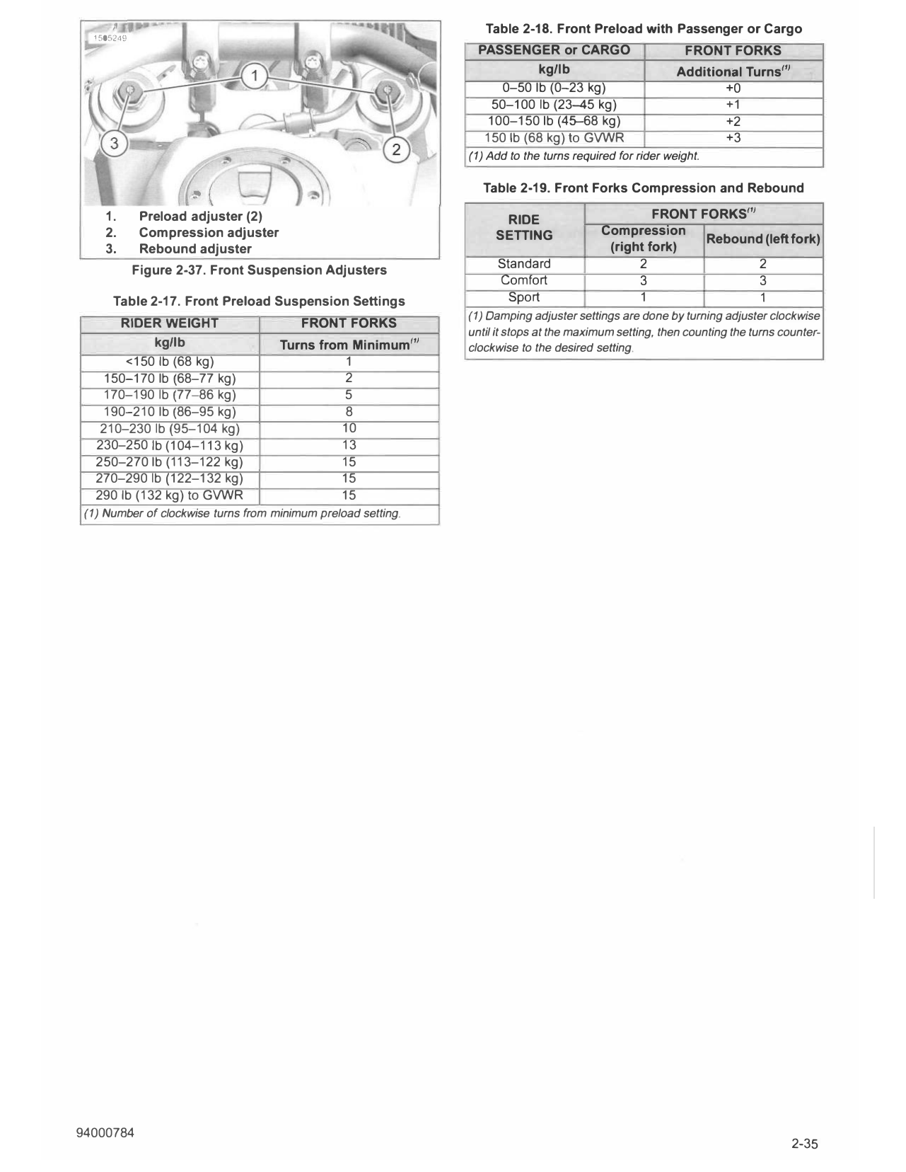
Table 2-18. Front Preload with Passenger or Cargo
PASSENGER or CARGO FRONT FORKS
kg/lb Additional Turns''1
0-50 lb (0-23 kg) +0
50-100 lb (23-45 kg) +1
100-150 lb (45-68 kg) +2
150 lb (68 kg) to GVWR +3
(1) Add to the turns required for rider weight.
Table 2-19. Front Forks Compression and Rebound
1. Preload adjuster (2) RIDE FRONT FORKS''1
2. Compression adjuster SETTING Compression
Rebound (left fork)
3. Rebound adjuster (right fork)
Figure 2-37. Front Suspension Adjusters Standard 2 2
Comfort 3 3
Table 2-17. Front Preload Suspension Settings Sport 1 1
(1) Damping adjuster settings are done by turning adjuster clockwise
RIDER WEIGHT FRONT FORKS
until it stops at the maximum setting, then counting the turns counter-
kg/lb Turns from Minimum''1 clockwise to the desired setting.
<150 lb (68 kg) 1
150-170 lb (68-77 kg) 2
170-190 lb (77-86 kg) 5
190-210 lb (86-95 kg) 8
210-230 lb (95-104 kg) 10
230-250 lb (104-113 kg) 13
250-270 lb (113-122 kg) 15
270-290 lb (122-132 kg) 15
290 lb (132 kg) to GVWR 15
(1) Number of clockwise turns from minimum preload setting.