8.4 Starter
Fragment manuala — str. 387–388
📋 Tekst do skopiowania (OCR/wyszukiwanie)
STARTER 8.4
PREPARE 5. Connect HO2S connectors (2).
1. Disconnect negative battery cable. See POWER
r,!e2325
DISCONNECT (Page 8-4).
2. Remove engine guard (if equipped). See ENGINE
GUARDS (Page 3-94).
3. Remove right and left fairing lowers. See FAIRING
LOWERS (Page 3-90).
4. Position radiator out-of-the-way. See RADIATOR
(Page 7-18).
REMOVE
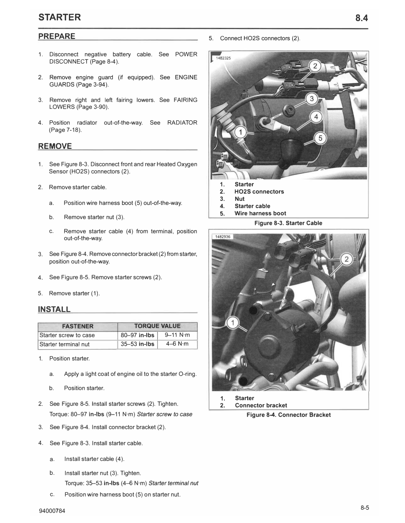
1. See Figure 8-3. Disconnect front and rear Heated Oxygen
Sensor (HO2S) connectors (2).
2. Remove starter cable. 1. Starter
2. H02S connectors
3. Nut
a. Position wire harness boot (5) out-of-the-way.
4. Starter cable
5. Wire harness boot
b. Remove starter nut (3).
Figure 8-3. Starter Cable
c. Remove starter cable (4) from terminal, position
out-of-the-way.
3. See Figure 8-4. Remove connector bracket (2) from starter,
position out-of-the-way.
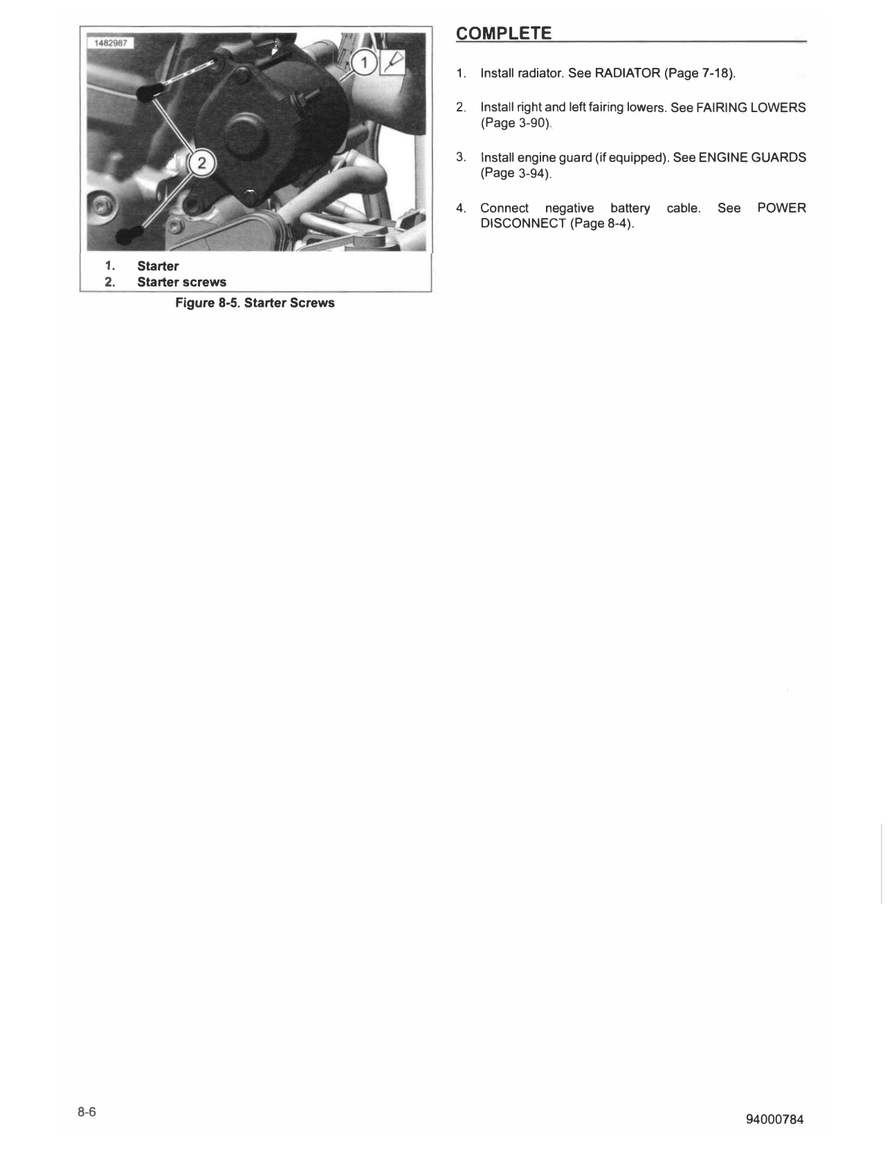
4. See Figure 8-5. Remove starter screws (2).
5. Remove starter (1).
INSTALL
FASTENER TORQUE VALUE
Starter screw to case 80-97 in-lbs I
9-11 N·m
Starter terminal nut 35-53 in-lbs I 4-6 N·m
1. Position starter.
a. Apply a light coat of engine oil to the starter O-ring.
b. Position starter.
1. Starter
2. See Figure 8-5. Install starter screws (2). Tighten. 2. Connector bracket
Torque: 80-97 in-lbs (9-11 N·m) Starter screw to case Figure 8-4. Connector Bracket
3. See Figure 8-4. Install connector bracket (2).
4. See Figure 8-3. Install starter cable.
a. Install starter cable (4).
b. Install starter nut (3). Tighten.
Torque: 35-53 in-lbs (4-6 N·m) Starter terminal nut
c. Position wire harness boot (5) on starter nut.
COMPLETE
1. Install radiator. See RADIATOR (Page 7-18).
2. Install right and left fairing lowers. See FAIRING LOWERS
(Page 3-90).
3. Install engine guard (if equipped). See ENGINE GUARDS
(Page 3-94).
4. Connect negative battery cable. See POWER
DISCONNECT (Page 8-4).
1. Starter
2. Starter screws
Figure 8-5. Starter Screws