🏍️ PAN AMERICA SERWIS

6.3 Air Box

Fragment manuala — str. 317–318

📋 Tekst do skopiowania (OCR/wyszukiwanie)
AIR BOX                                                                                                                     6.3

PREPARE                                                                See Figure 6-4. Install air box base.

1.   Remove main fuse. See POWER DISCONNECT                            a.   Install air box base (12). Verify the velocity stacks
     (Page 8-4)                                                             are properly seated.

2. Remove seat. See SEAT (Page 3-113).                                 b.   Verify inserts ( 14) are present in the eight mounting
                                                                            holes.
3.   Remove fuel tank. See FUEL TANK (Page 6-13)
                                                                       c.   See Figure 6-3. Install air box breather tube (1) to
                                                                            front cylinder head breather bolt.
REMOVE
                                                                       d.   See Figure 6-4. Hand start screws (1-8) in sequence
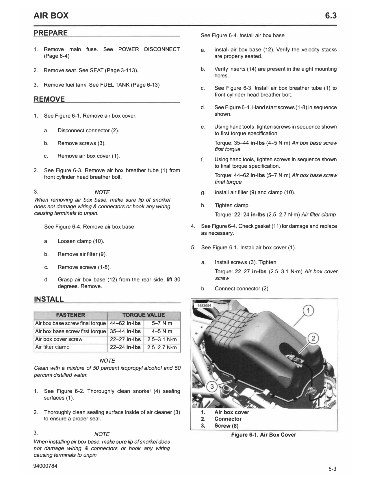
1.   See Figure 6-1. Remove air box cover.                                  shown.

                                                                       e.   Using hand tools, tighten screws in sequence shown
     a.    Disconnect connector (2).
                                                                            to first torque specification.
     b.    Remove screws (3).                                                Torque: 35-44 in-lbs (4-5 N·m) Air box base screw
                                                                             first torque
     c.    Remove air box cover (1).
                                                                       f.   Using hand tools, tighten screws in sequence shown
                                                                            to final torque specification.
2.   See Figure 6-3. Remove air box breather tube (1) from
     front cylinder head breather bolt.                                      Torque: 44-62 in-lbs (5-7 N·m) Air box base screw
                                                                             final torque
3.                       NOTE                                          g.    Install air filter (9) and clamp (10).
When removing air box base, make sure lip of snorkel
does not damage wiring & connectors or hook any wiring                 h.    Tighten clamp.
causing terminals to unpin.                                                  Torque: 22-24 in-lbs (2.5-2.7 N·m) Air filter clamp

     See Figure 6-4. Remove air box base.                         4.   See Figure 6-4. Check gasket (11) for damage and replace
                                                                       as necessary.
     a.    Loosen clamp (10).
                                                                  5.   See Figure 6-1. Install air box cover (1).
     b.    Remove air filter (9).
                                                                       a.    Install screws (3). Tighten.
     c.    Remove screws (1-8).
                                                                             Torque: 22-27 in-lbs (2.5-3.1 N·m) Air box cover
     d.    Grasp air box base (12) from the rear side, lift 30               screw
           degrees. Remove.                                            b.    Connect connector (2).

INSTALL

          FASTENER                      TORQUE VALUE
Air box base screw final torque     44-62 in-lbs     5-7 N·m
Air box base screw first torque     35-44 in-lbs     4-5 N·m
Air box cover screw                 22-27 in-lbs   2.5-3.1 N·m
Air filter clamp                    22-24 in-lbs   2.5-2.7 N·m

                          NOTE
Clean with a mixture of 50 percent isopropyl alcohol and 50
percent distilled water.

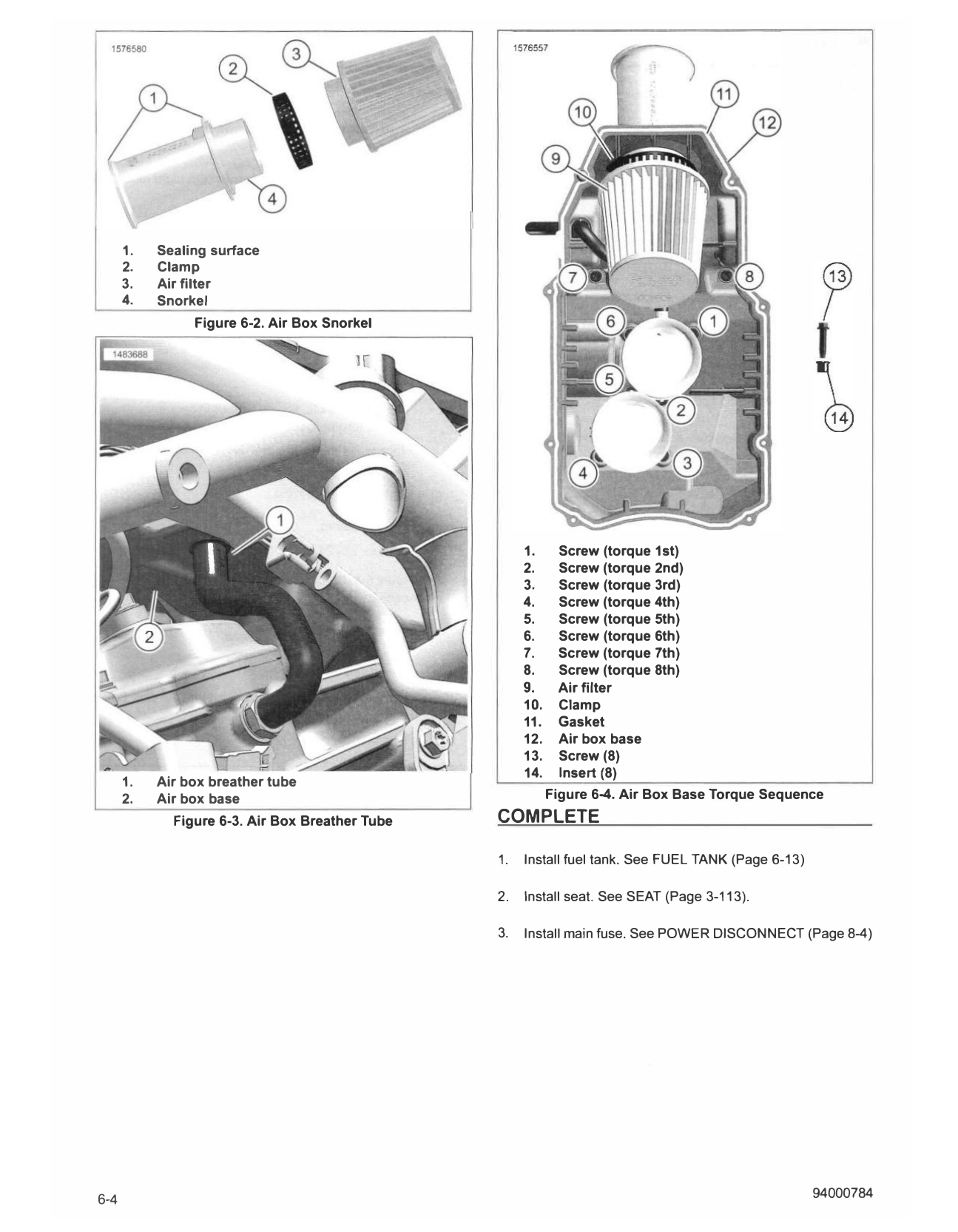
1.   See Figure 6-2. Thoroughly clean snorkel (4) sealing
     surfaces (1).

2.   Thoroughly clean sealing surface inside of air cleaner (3)        1.   Air box cover
     to ensure a proper seal.                                          2.   Connector
                                                                       3.   Screw (8)
3.                        NOTE                                                      Figure 6-1. Air Box Cover
When installing air box base, make sure lip of snorkel does
not damage wiring & connectors or hook any wiring
causing terminals to unpin.

94000784                                                                                                                      6-3
      1.   Sealing surface
      2.   Clamp
      3.   Air filter
      4.   Snorkel
                Figure 6-2. Air Box Snorkel

                                                      1.     Screw (torque 1st)
                                                      2.     Screw (torque 2nd)
                                                      3.     Screw (torque 3rd)
                                                      4.     Screw (torque 4th)
                                                      5.     Screw (torque 5th)
                                                      6.     Screw (torque 6th)
                                                      7.     Screw (torque 7th)
                                                      8.     Screw (torque 8th)
                                                      9.     Air filter
                                                      10.    Clamp
                                                      11.    Gasket
                                                      12.    Air box base
                                                      13.    Screw (8)
                                                      14.    Insert (8)
      1.   Air box breather tube
      2.   Air box base                                     Figure 6-4. Air Box Base Torque Sequence
             Figure 6-3. Air Box Breather Tube   COMPLETE

                                                 1.   Install fuel tank. See FUEL TANK (Page 6-13)

                                                 2.   Install seat. See SEAT (Page 3-113).

                                                 3.   Install main fuse. See POWER DISCONNECT (Page 8-4)

6-4                                                                                                  94000784