4.15 Camshaft Sprocket And Timing Chain
Fragment manuala — str. 228–234
📋 Tekst do skopiowania (OCR/wyszukiwanie)
CAMSHAFT SPROCKET AND TIMING CHAIN 4.15
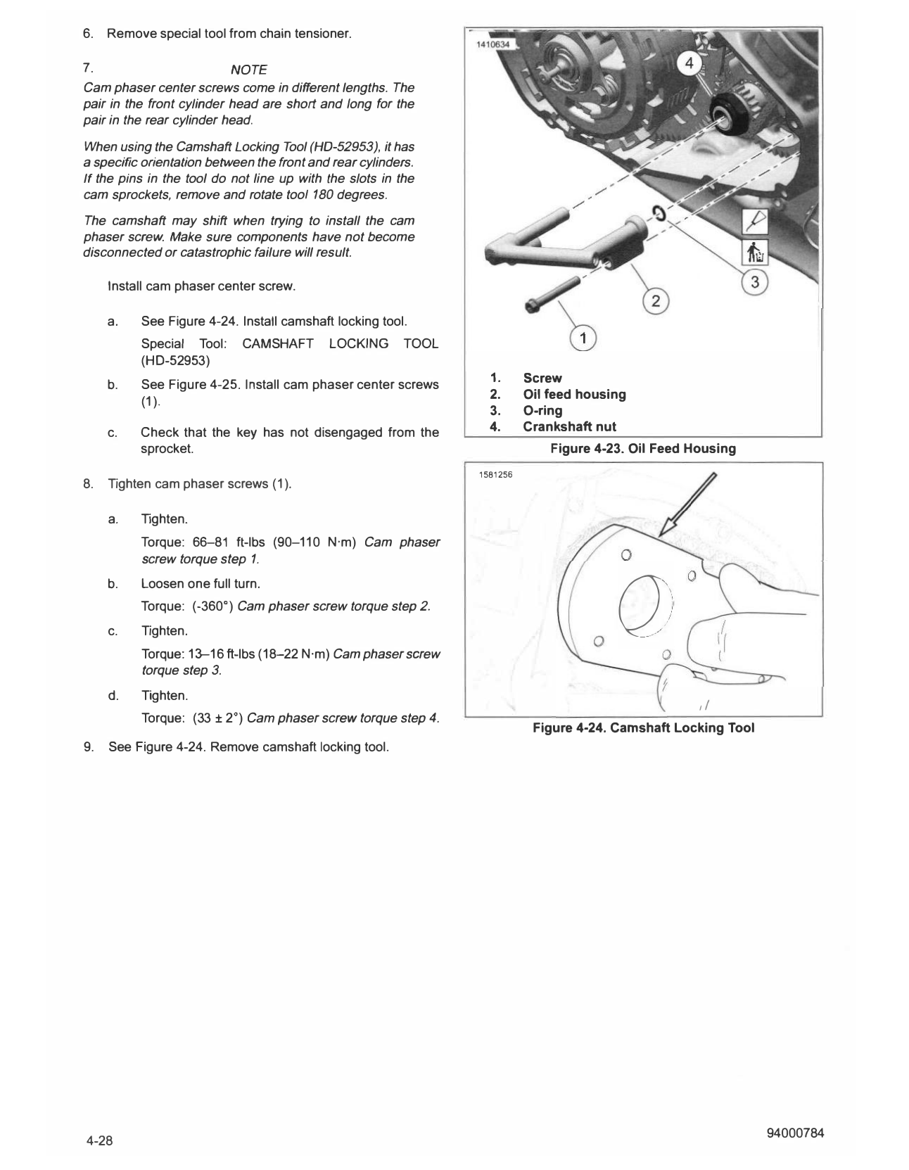
PREPARE b. Remove oil feed housing (2).
c. Remove and discard a-ring (3).
PART NUMBER TOOL NAME
HD-52956 CRANKSHAFT LOCKING TOOL
2. If removing lower gear: Remove crankshaft nut (4).
1. Remove main fuse. See POWER DISCONNECT
(Page 8-4). 3. Remove cam phaser center screw.
NOTE
2. I nstall crankshaft locking tool. See CRANKSHAFT When using the special tool, it has specific orientation
LOCKOUT (Page 4-18). between the front and rear cylinders. If the pins do not line
Special Tool: CRANKSHAFT LOCKING TOOL (HD-52956) up with the slots in the sprockets, remove and rotate tool
180 degrees.
a. Move radiator assembly to allow access to crankshaft
lockout plug.
a. See Figure 4-24. I nstall camshaft locking tool.
3. Remove skid plate. See SKI D PLATE (Page 3-92). Special Tool: CAMSHAFT LOCKING TOOL
(HD-52953)
4. Remove exhaust header pipe. See EXHAUST SYSTEM b. See Figure 4-25. Remove cam phaser center screws
(Page 6-37). (1).
5. Remove primary cover and clutch baffle. See PRIMARY c. Remove camshaft locking tool.
COVER (Page 4-49).
4. See Figure 4-26. I nstall cam chain retention tool to end of
6. Front Sprockets: crankshaft to keep timing chain in place.
Special Tool: CAM CHAIN RETENTION TOOL (HD-52951)
a. Remove seat. See SEAT (Page 3-113).
5. Secure piston in chain tensioner housing. See
b. Remove fuel tank. See FUEL TANK (Page 6-13). SECONDARY BALANCER (Page 4-31).
c. Remove airbox assembly. See AIR BOX a. Push piston into cam tensioner housing.
(Page 6-3).
b. See Figure 4-27. I nstall cam chain retraction pin (1)
7. Rear Sprockets: in hole (2).
Special Tool: CAM CHAIN RETRACTION PIN
a. Remove seat. See SEAT (Page 3-113). (HD-53023)
b. Remove fuel tank. See FUEL TANK (Page 6-13). 6. See Figure 4-28. Remove sprockets and chain.
c. Remove cylinder head cover caddy. See CYLINDER a. Remove screw (5). Use impact wrench with short
HEAD COVER CADDY (Page 8-60). bursts.
8. Remove camshaft cover. See CAMSHAFT COVERS b. Detach dynamic chain guide assembly (6) and lower
(Page 4-21). into engine case.
c. Detach fixed chain guide assembly (4) and lower
9. Remove cylinder head cover. See CYLINDER HEA D
into engine case.
COVERS (Page 4-19).
d. Remove sprockets (2, 3).
10. Remove phaser solenoids with plate assembly. See
PHASER SOLENOIDS (Page 4-22). e. Remove both chain guide assemblies (4, 6).
REMOVE f. See Figure 4-26. Remove cam chain retention tool
from crankshaft.
PART NUMBER TOOLNAME Special Tool: CAM CHAIN RETENTION TOOL
HD-52951 CAM CHAIN RETENTION TOOL (HD-52951)
HD-52953 CAMSHAFT LOCKING TOOL g. Remove timing chain (1).
HD-53023 CAM CHAIN RETRACTION PIN
7. See Figure 4-29. Remove camshaft drive sprocket.
1. See Figure 4-23. Remove oil feed housing.
a. Remove locknut (4).
a. Remove screw (1 ).
b. Remove camshaft drive sprocket (3).
c. Remove key (2).
8. Remove top hat screw (1).
9. Remove chain tensioner. See SECONDARY BALANCER
(Page 4-31).
10. Remove secondary balancer. See SECONDARY
BALANCER (Page 4-31).
CAM TIMING
PART NUMBER TOOL NAME
HD-52951 CAM CHAIN RETENTION TOOL
CONSUMABLE PART NUMBER
SCREAM IN' 11300002
EAGLE
ASSEMBLY LUBE
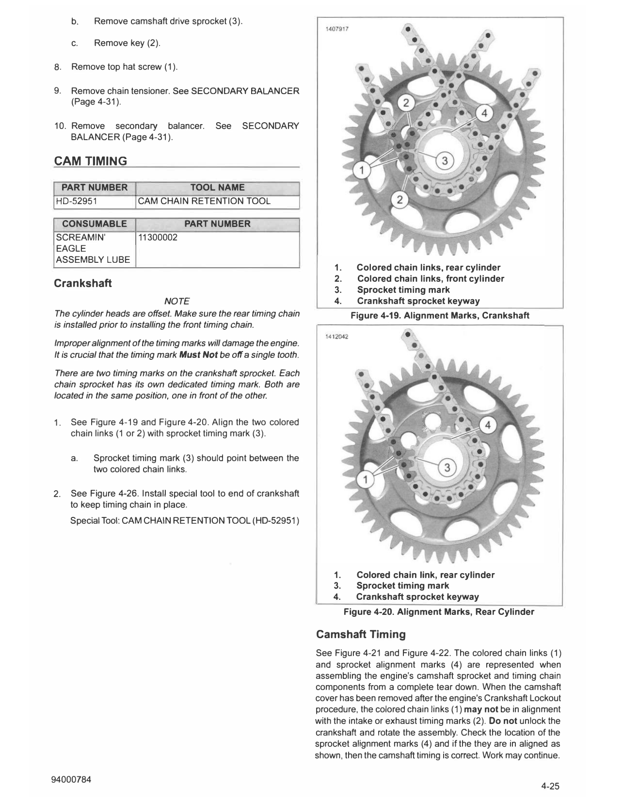
1. Colored chain links, rear cylinder
2. Colored chain links, front cylinder
Crankshaft
3. Sprocket timing mark
NOTE 4. Crankshaft sprocket keyway
The cylinder heads are offset. Make sure the rear timing chain Figure 4-19. Alignment Marks, Crankshaft
is installed prior to installing the front timing chain.
Improper alignment of the timing marks will damage the engine.
It is crucial that the timing mark Must Not be off a single tooth.
There are two timing marks on the crankshaft sprocket. Each
chain sprocket has its own dedicated timing mark. Both are
located in the same position, one in front of the other.
1. See Figure 4-19 and Figure 4-20. Align the two colored
chain links (1 or 2) with sprocket timing mark (3).
a. Sprocket timing mark (3) should point between the
two colored chain links.
2. See Figure 4-26. Install special tool to end of crankshaft
to keep timing chain in place.
Special Tool: CAM CHAIN RETENTION TOOL (HD-52951)
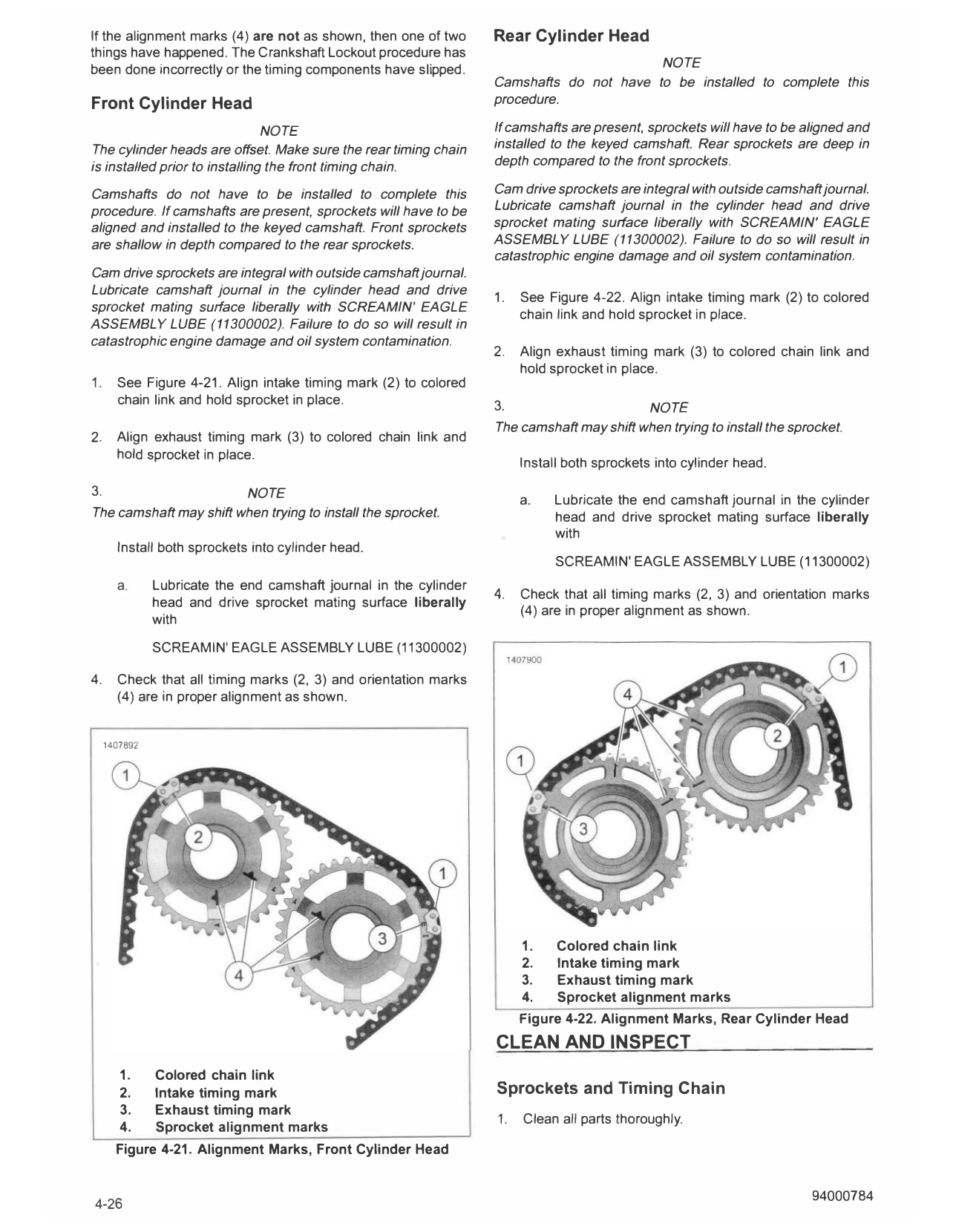
1. Colored chain link, rear cylinder
3. Sprocket timing mark
4. Crankshaft sprocket keyway
Figure 4-20. Alignment Marks, Rear Cylinder
Camshaft Timing
See Figure 4-21 and Figure 4-22. The colored chain links (1)
and sprocket alignment marks (4) are represented when
assembling the engine's camshaft sprocket and timing chain
components from a complete tear down. When the camshaft
cover has been removed after the engine's Crankshaft Lockout
procedure, the colored chain links (1) may not be in alignment
with the intake or exhaust timing marks (2). Do not unlock the
crankshaft and rotate the assembly. Check the location of the
sprocket alignment marks (4) and if the they are in aligned as
shown, then the camshaft timing is correct. Work may continue.
If the alignment marks (4) are not as shown, then one of two Rear Cylinder Head
things have happened. The Crankshaft Lockout procedure has
been done incorrectly or the timing components have slipped. NOTE
Camshafts do not have to be installed to complete this
Front Cylinder Head procedure.
NOTE If camshafts are present, sprockets will have to be aligned and
The cylinder heads are offset. Make sure the rear timing chain installed to the keyed camshaft. Rear sprockets are deep in
is installed prior to installing the front timing chain. depth compared to the front sprockets.
Camshafts do not have to be installed to complete this Cam drive sprockets are integral with outside camshaftjournal.
procedure. If camshafts are present, sprockets will have to be Lubricate camshaft journal in the cylinder head and drive
aligned and installed to the keyed camshaft. Front sprockets sprocket mating surface liberally with SCREAMIN' EAGLE
are shallow in depth compared to the rear sprockets. ASSEMBLY LUBE (11300002). Failure to do so will result in
catastrophic engine damage and oil system contamination.
Cam drive sprockets are integral with outside camshaftjournal.
Lubricate camshaft journal in the cylinder head and drive
1. See Figure 4-22. Align intake timing mark (2) to colored
sprocket mating surface liberally with SCREAMIN' EAGLE
chain link and hold sprocket in place.
ASSEMBLY LUBE (11300002). Failure to do so will result in
catastrophic engine damage and oil system contamination.
2. Align exhaust timing mark (3) to colored chain link and
hold sprocket in place.
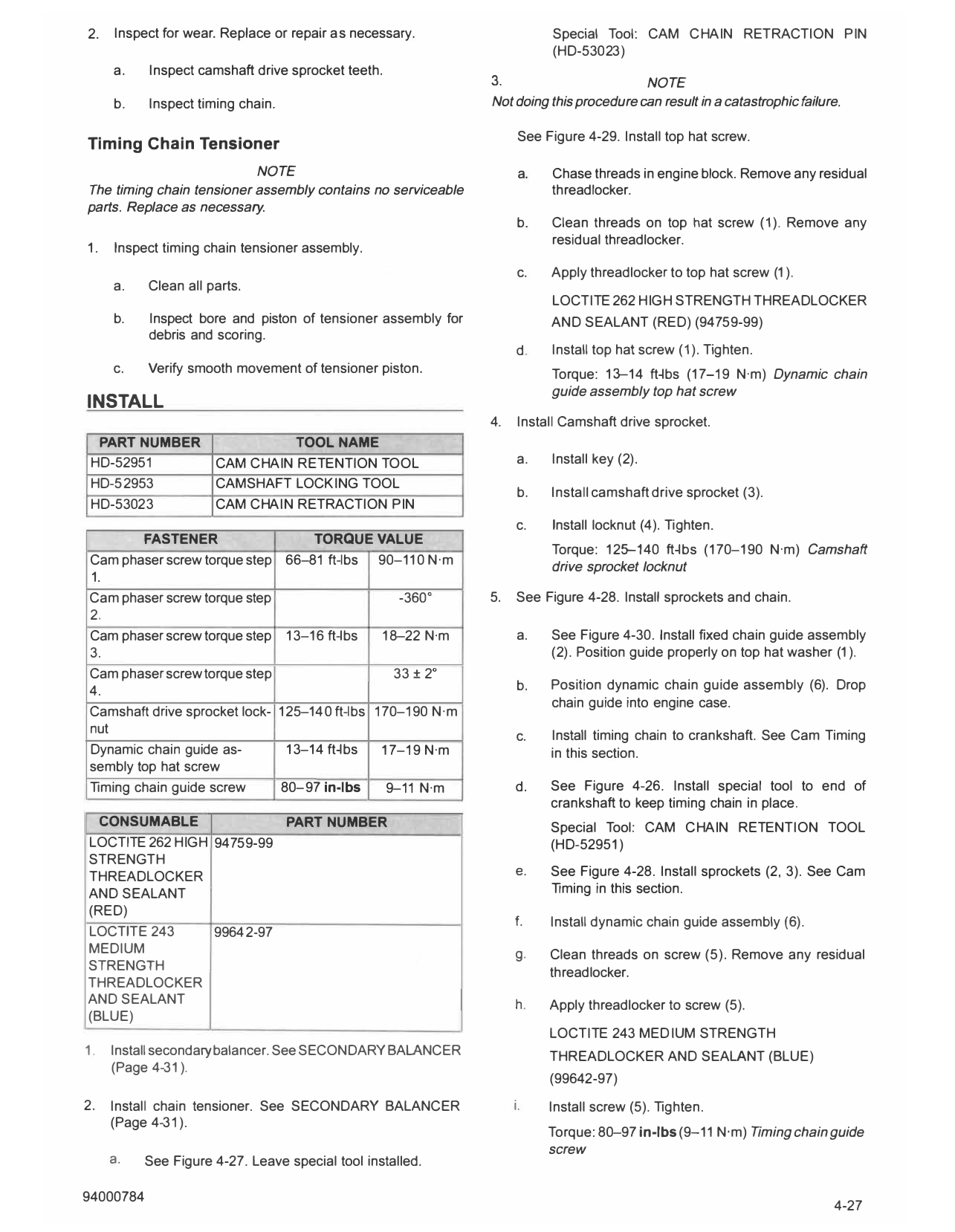
1. See Figure 4-21. Align intake timing mark (2) to colored
chain link and hold sprocket in place. 3. NOTE
The camshaft may shift when trying to install the sprocket.
2. Align exhaust timing mark (3) to colored chain link and
hold sprocket in place.
Install both sprockets into cylinder head.
3. NOTE a. Lubricate the end camshaft journal in the cylinder
The camshaft may shift when trying to install the sprocket. head and drive sprocket mating surface liberally
with
Install both sprockets into cylinder head.
SCREAMIN' EAGLE ASSEMBLY LUBE (11300002)
a. Lubricate the end camshaft journal in the cylinder
4. Check that all timing marks (2, 3) and orientation marks
head and drive sprocket mating surface liberally
(4) are in proper alignment as shown.
with
SCREAM IN' EAGLE ASSEMBLY LUBE (11300002)
4. Check that all timing marks (2, 3) and orientation marks
(4) are in proper alignment as shown.
1407892
1. Colored chain link
2. Intake timing mark
3. Exhaust timing mark
4. Sprocket alignment marks
Figure 4-22. Alignment Marks, Rear Cylinder Head
CLEAN AND INSPECT
1. Colored chain link
2. Intake timing mark Sprockets and Timing Chain
3. Exhaust timing mark
1. Clean all parts thoroughly.
4. Sprocket alignment marks
Figure 4-21. Alignment Marks, Front Cylinder Head
2. Inspect for wear. Replace or repair as necessary. Special Tool: CAM CHAIN RET RACTION PIN
(HD-53023)
a. Inspect camshaft drive sprocket teeth.
3. NOTE
b. Inspect timing chain. Not doing this procedure can result in a catastrophic failure.
See Figure 4-29 . Install top hat screw.
Timing Chain Tensioner
NOTE a. Chase threads in engine block. Remove any residual
The timing chain tensioner assembly contains no serviceable threadlocker.
parts. Replace as necessary.
b. Clean threads on top hat screw (1 ). Remove any
residual threadlocker.
1. Inspect timing chain tensioner assembly.
c. Apply threadlocker to top hat screw (1 ).
a. Clean all parts.
LOCTITE 262 HIGH ST RENGTH THREADLOCKER
b. Inspect bore and piston of tensioner assembly for AND SEALANT ( RED) (94759 -99 )
debris and scoring.
d. Install top hat screw (1 ). Tighten.
c. Verify smooth movement of tensioner piston. Torque: 13--14 ft-lbs (17-19 N·m) Dynamic chain
guide assembly top hat screw
INSTALL
4. Install Camshaft drive sprocket.
PART NUMBER TOOL NAME
HD-52951 CAM CHAIN RETENTION TOOL a. Install key (2).
HD-52953 CAMSHAFT LOCKING TOOL
b. Install camshaft drive sprocket ( 3).
HD-5302 3 CAM CHAIN RET RACTION PIN
c. Install locknut (4). Tighten.
FASTENER TORQUE VALUE
Torque: 125--140 ft-lbs ( 170-190 N·m) Camshaft
Cam phaser screw torque step 66-81 ft-lbs 90-110 N·m
drive sprocket locknut
1.
Cam phaser screw torque step - 360 ° 5. See Figure 4-28 . Install sprockets and chain.
2.
Cam phaser screw torque step 1 3-16 ft-lbs 18--22 N·m a. See Figure 4- 30 . Install fixed chain guide assembly
3. (2). Position guide properly on top hat washer (1 ).
Cam phaser screw torque step 33 ± 2 °
4. b. Position dynamic chain guide assembly (6). Drop
chain guide into engine case.
Camshaft drive sprocket lock- 125-140 ft-lbs 170-190 N·m
nut
c. Install timing chain to crankshaft. See Cam Timing
Dynamic chain guide as- 1 3-14 ft-lbs 17-19 N·m in this section.
sembly top hat screw
Timing chain guide screw 80-97 in-lbs 9-11 N·m d. See Figure 4-26 . Install special tool to end of
crankshaft to keep timing chain in place.
CONSUMABLE PART NUMBER Special Tool: CAM CHAIN RETENTION TOOL
LOCTITE 262 HIGH 94759 -99 (HD-52951 )
ST RENGTH
THREADLOCKER e. See Figure 4-28 . Install sprockets (2, 3). See Cam
AND SEALANT Timing in this section.
( RED)
f. Install dynamic chain guide assembly (6).
LOCTIT E 243 99642-97
MEDIUM g. Clean threads on screw (5). Remove any residual
STRENGTH threadlocker.
THREADLOCKER
AND SEALANT h. Apply threadlocker to screw (5).
(BLUE)
LOCTITE 243 MEDIUM ST RENGTH
1. Install secondary balancer. See SECONDARYBALANCER THREADLOCKER AND SEALANT (BLUE)
(Page 4-31 ).
(99642 -97 )
2. Install chain tensioner. See SECONDARY BALANCER i. Install screw (5). Tighten.
(Page 4-31 ).
Torque: 80--97 in-lbs (9-11 N·m) Timing chain guide
screw
a. See Figure 4-27 . Leave special tool installed.
6. Remove special tool from chain tensioner.
7. NOTE
Cam phaser center screws come in different lengths. The
pair in the front cylinder head are short and long for the
pair in the rear cylinder head.
When using the Camshaft Locking Tool (HD-52953), it has
a specific orientation between the front and rear cylinders.
If the pins in the tool do not line up with the slots in the
cam sprockets, remove and rotate tool 180 degrees.
The camshaft may shift when trying to install the cam
phaser screw. Make sure components have not become
disconnected or catastrophic failure will result.
Install cam phaser center screw.
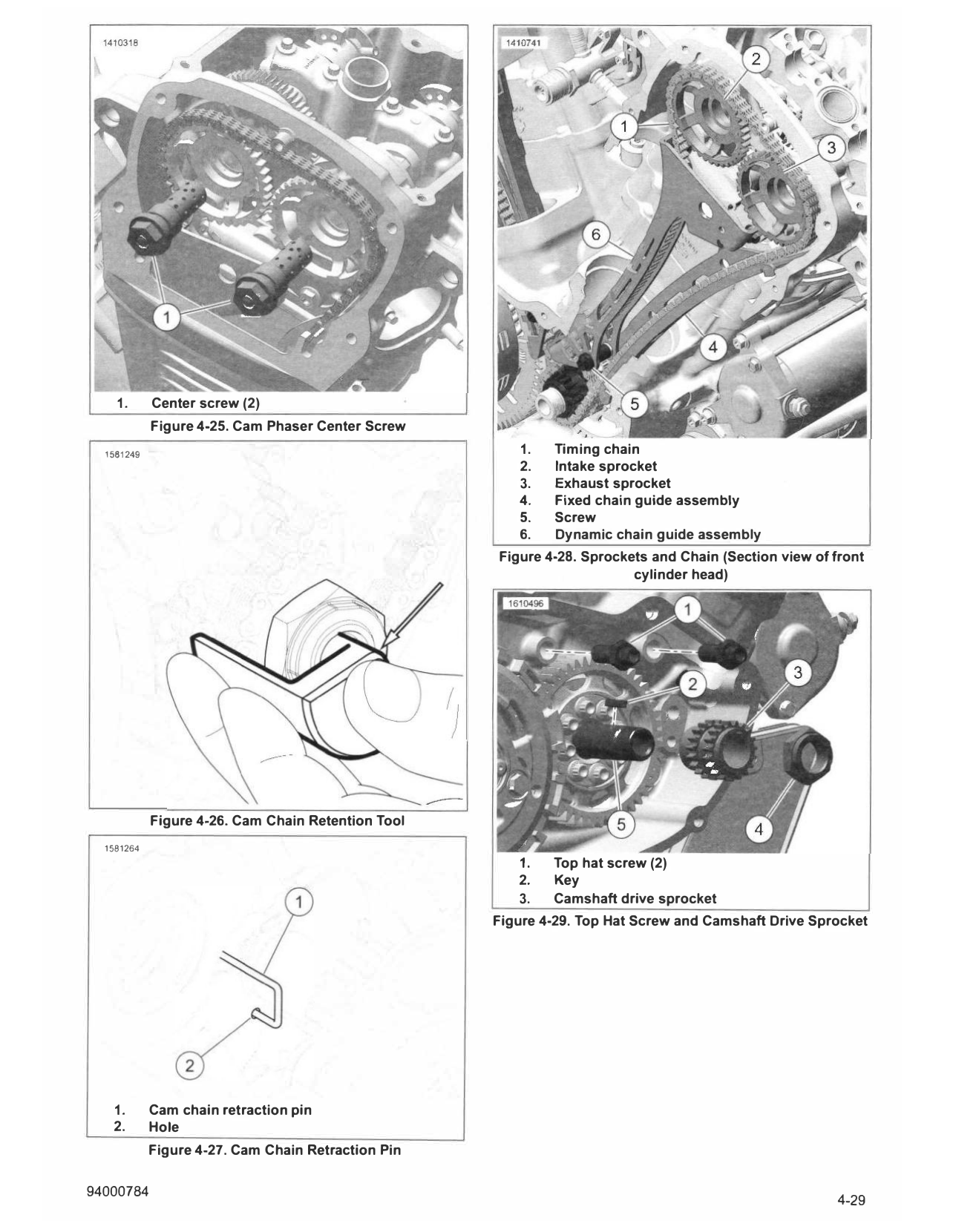
a. See Figure 4-24. Install camshaft locking tool.
Special Tool: CAMSHAFT LOCKING TOOL
(HD-52953)
1. Screw
b. See Figure 4-25. Install cam phaser center screws
2. Oil feed housing
(1 ).
3. O-ring
c. Check that the key has not disengaged from the 4. Crankshaft nut
sprocket. Figure 4-23. Oil Feed Housing
1581256
8. Tighten cam phaser screws (1).
a. Tighten.
Torque: 66-81 ft-lbs (90-110 N·m) Cam phaser
screw torque step 1.
b. Loosen one full turn.
c.
Torque: (-360 ° ) Cam phaser screw torque step 2.
Tighten.
Torque: 13-16 ft-lbs (18-22 N·m) Cam phaser screw
Q)
torque step 3.
d. Tighten.
I I
Torque: (33 ± 2° ) Cam phaser screw torque step 4.
Figure 4-24. Camshaft Locking Tool
9. See Figure 4-24. Remove camshaft locking tool.
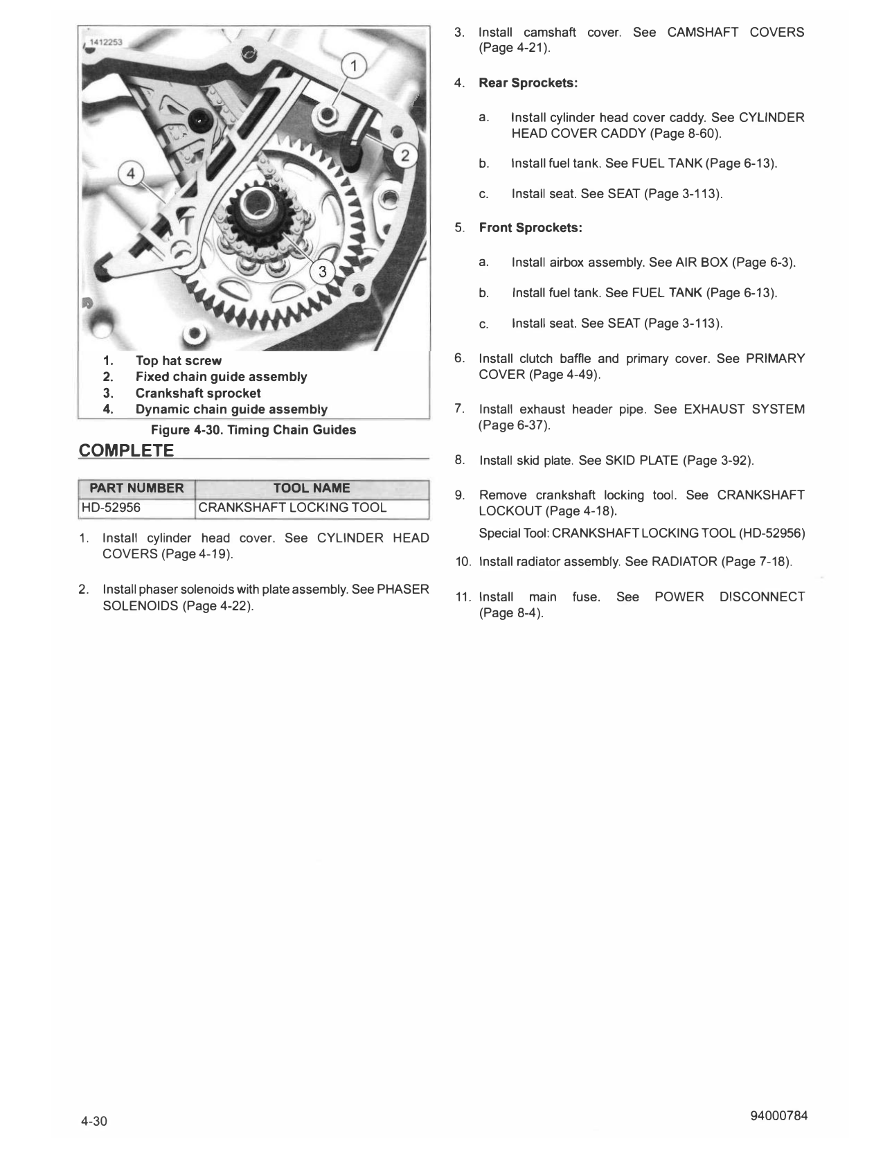
1. Center screw (2)
Figure 4-25. Cam Phaser Center Screw
1581249 1. Timing chain
2. Intake sprocket
3. Exhaust sprocket
4. Fixed chain guide assembly
5. Screw
6. Dynamic chain guide assembly
Figure 4-28. Sprockets and Chain (Section view of front
cylinder head)
Figure 4-26. Cam Chain Retention Tool
1581264
1. Top hat screw (2)
2. Key
3. Camshaft drive sprocket
Figure 4-29. Top Hat Screw and Camshaft Drive Sprocket
1. Cam chain retraction pin
2. Hole
Figure 4-27. Cam Chain Retraction Pin
3. Install camshaft cover. See CAMSHAFT COVERS
(Page 4-21 ).
4. Rear Sprockets:
a. Install cylinder head cover caddy. See CYLINDER
HEAD COVER CADDY (Page 8-60).
b. Install fuel tank. See FUEL TANK (Page 6-13).
c. Install seat. See SEAT (Page 3-113).
5. Front Sprockets:
a. Install airbox assembly. See AIR BOX (Page 6-3).
b. Install fuel tank. See FUEL TANK (Page 6-13).
c. Install seat. See SEAT (Page 3-113).
1. Top hat screw 6. Install clutch baffle and primary cover. See PRIMARY
2. Fixed chain guide assembly COVER (Page 4-49).
3. Crankshaft sprocket
4. Dynamic chain guide assembly 7. Install exhaust header pipe. See EXHAUST SYSTEM
Figure 4-30. Timing Chain Guides (Page 6-37).
COMPLETE 8. Install skid plate. See SKID PLATE (Page 3-92).
PART NUMBER TOOL NAME 9. Remove crankshaft locking tool. See CRANKSHAFT
HD-52956 CRANKSHAFT LOCKING TOOL LOCKO U T (Page 4-18).
1. Install cylinder head cover. See CYLINDER HEAD Special Tool: CRANKSHAFT LOCKING TOOL (HD-52956)
COVERS (Page 4-19).
10. Install radiator assembly. See RADIATOR (Page 7-18).
2. Install phaser solenoids with plate assembly. See PHASER
11. Install main fuse. See POWER DISCONNECT
SOLENOIDS (Page 4-22).
(Page 8-4).
4-30 94000784