B.4 Torque Conversion
Fragment manuala — str. 494–512


📋 Tekst do skopiowania (OCR/wyszukiwanie)
TORQUE CONVERSION 8.4
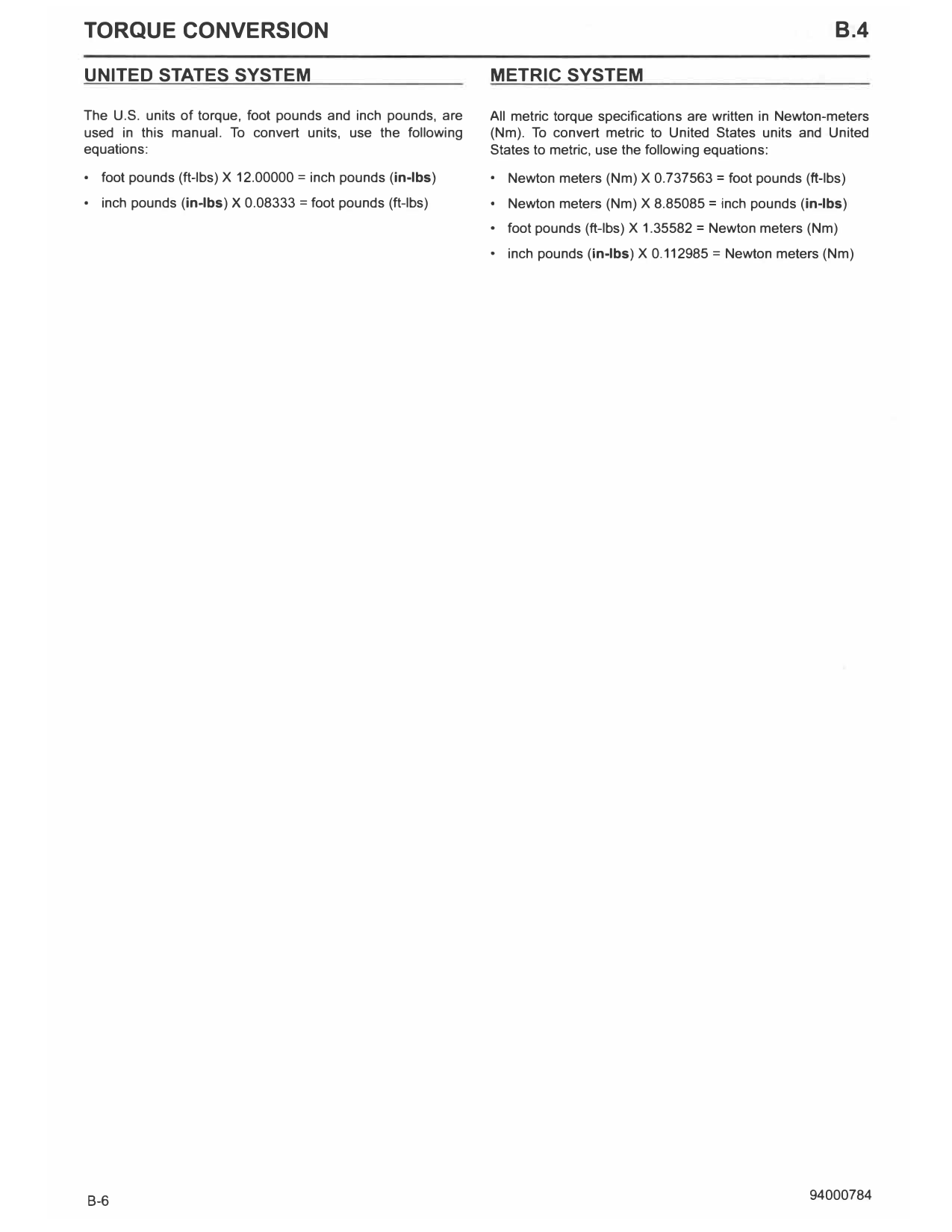
UNITED STATES SYSTEM METRIC SYSTEM
T he U.S. units of torque, foot pounds and inch pounds, are All metric torque specifications are written in Newton-meters
used in this manual. To convert units, use the following (Nm). To convert metric to United States units and United
equations: States to metric, use the following equations:
• foot pounds (ft-lbs) X 12.00000 = inch pounds (in-lbs) • Newton meters (Nm) X 0.737563 = foot pounds (ft-lbs)
• inch pounds (in-lbs} X 0.08333 = foot pounds (ft-lbs) • Newton meters (Nm) X 8.85085 = inch pounds (in-lbs)
• foot pounds (ft-lbs) X 1.35582 = Newton meters (Nm)
• inch pounds (in-lbs) X 0.112985 = Newton meters (Nm)
B-6 94000784
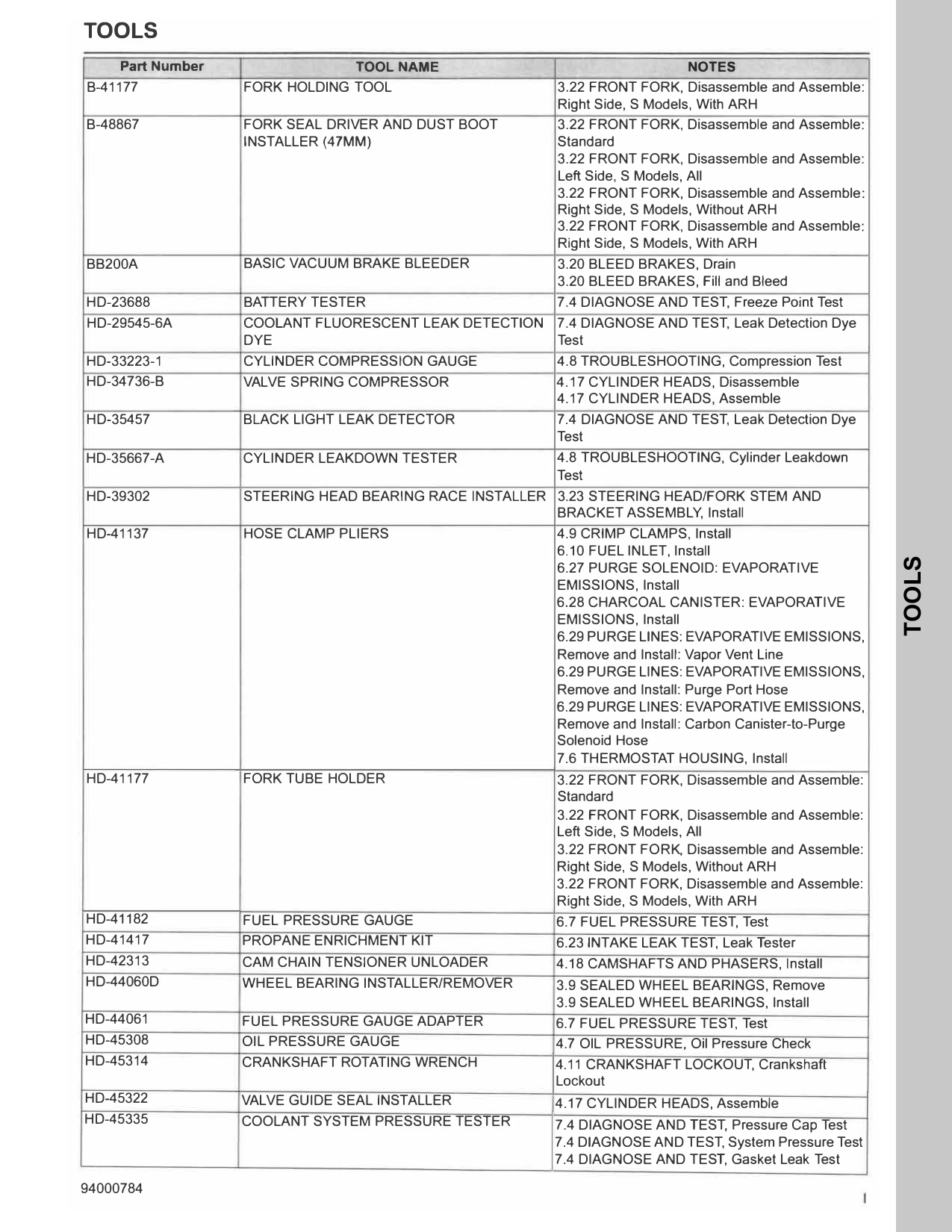
TOOLS
Part Number TOOLNAME NOTES
B-41177 FORK HOLDING TOOL 3.22 FRONT FORK, Disassemble and Assemble:
Right Side, S Models, With ARH
B-48867 FORK SEAL DRIVER AND DUST BOOT 3.22 FRONT FORK, Disassemble and Assemble:
INSTALLER (47MM) Standard
3.22 FRONT FORK, Disassemble and Assemble:
Left Side, S Models, All
3.22 FRONT FORK, Disassemble and Assemble:
Right Side, S Models, Without ARH
3.22 FRONT FORK, Disassemble and Assemble:
Right Side, S Models, With ARH
BB200A BASIC VACUUM BRAKE BLEEDER 3.20 BLEED BRAKES, Drain
3.20 BLEED BRAKES, Fill and Bleed
HD-23688 BATTERY TESTER 7.4 DIAGNOSE AND TEST, Freeze Point Test
HD-29545-6A COOLANT FLUORESCENT LEAK DETECTION 7.4 DIAGNOSE AND TEST, Leak Detection Dye
DYE Test
HD-33223-1 CYLINDER COMPRESSION GAUGE 4.8 TROUBLESHOOTING, Compression Test
HD-34736-B VALVE SPRING COMPRESSOR 4.17 CYLINDER HEADS, Disassemble
4.17 CYLINDER HEADS, Assemble
HD-35457 BLACK LIGHT LEAK DETECTOR 7.4 DIAGNOSE AND TEST, Leak Detection Dye
Test
HD-35667-A CYLINDER LEAKDOWN TESTER 4.8 TROUBLESHOOTING, Cylinder Leakdown
Test
HD-39302 STEERING HEAD BEARING RACE INSTALLER 3.23 STEERING HEAD/FORK STEM AND
BRACKET ASSEMBLY, Install
HD-41137 HOSE CLAMP PLIERS 4.9 CRIMP CLAMPS, Install
6.10 FUEL INLET, Install
TOOLS
6.27 PURGE SOLENOID: EVAPORATIVE
EMISSIONS, Install
6.28 CHARCOAL CANISTER: EVAPORAT IVE
EMISSIONS, Install
6.29 PURGE LINES: EVAPORATIVE EMISSIONS,
Remove and Install: Vapor Vent Line
6.29 PURGE LINES: EVAPORATIVE EMISSIONS,
Remove and Install: Purge Port Hose
6.29 PURGE LINES: EVAPORATIVE EMISSIONS,
Remove and Install: Carbon Canister-to-Purge
Solenoid Hose
7.6 THERMOSTAT HOUSING, Install
HD-41177 FORK TUBE HOLDER 3.22 FRONT FORK, Disassemble and Assemble:
Standard
3.22 FRONT FORK, Disassemble and Assemble:
Left Side, S Models, All
3.22 FRONT FORK, Disassemble and Assemble:
Right Side, S Models , Without ARH
3.22 FRONT FORK, Disassemble and Assemble:
Right Side, S Models, With ARH
HD-41182 FUEL PRESSURE GAUGE 6.7 FUEL PRESSURE TEST, Test
HD-41417 PROPANE ENRICHMENT KIT 6.23 INTAKE LEAK TEST, Leak Tester
HD-42313 CAM CHAIN TENSIONER UNLOADER 4.18 CAMSHAFTS AND PHASERS, Install
HD-44060D WHEEL BEARING INSTALLER/REMOVER 3.9 SEALED WHEEL BEARINGS, Remove
3.9 SEALED WHEEL BEARINGS, Install
HD-44061 FUEL PRESSURE GAUGE ADAPTER 6.7 FUEL PRESSURE TEST, Test
HD-45308 OIL PRESSURE GAUGE 4.7 OIL PRESSURE, Oil Pressure Check
HD-45314 CRANKSHAFT ROTATING WRENCH 4.11 CRANKSHAFT LOCKOUT, Crankshaft
Lockout
HD-45322 VALVE GUIDE SEAL INSTALLER 4.17 CYLINDER HEADS, Assemble
HD-45335 COOLANT SYSTEM PRESSURE TESTER 7.4 DIAGNOSE AND T EST, Pressure Cap Test
7.4 DIAGNOSE AND TEST, System Pressure Test
7.4 DIAGNOSE AND TEST, Gasket Leak Test
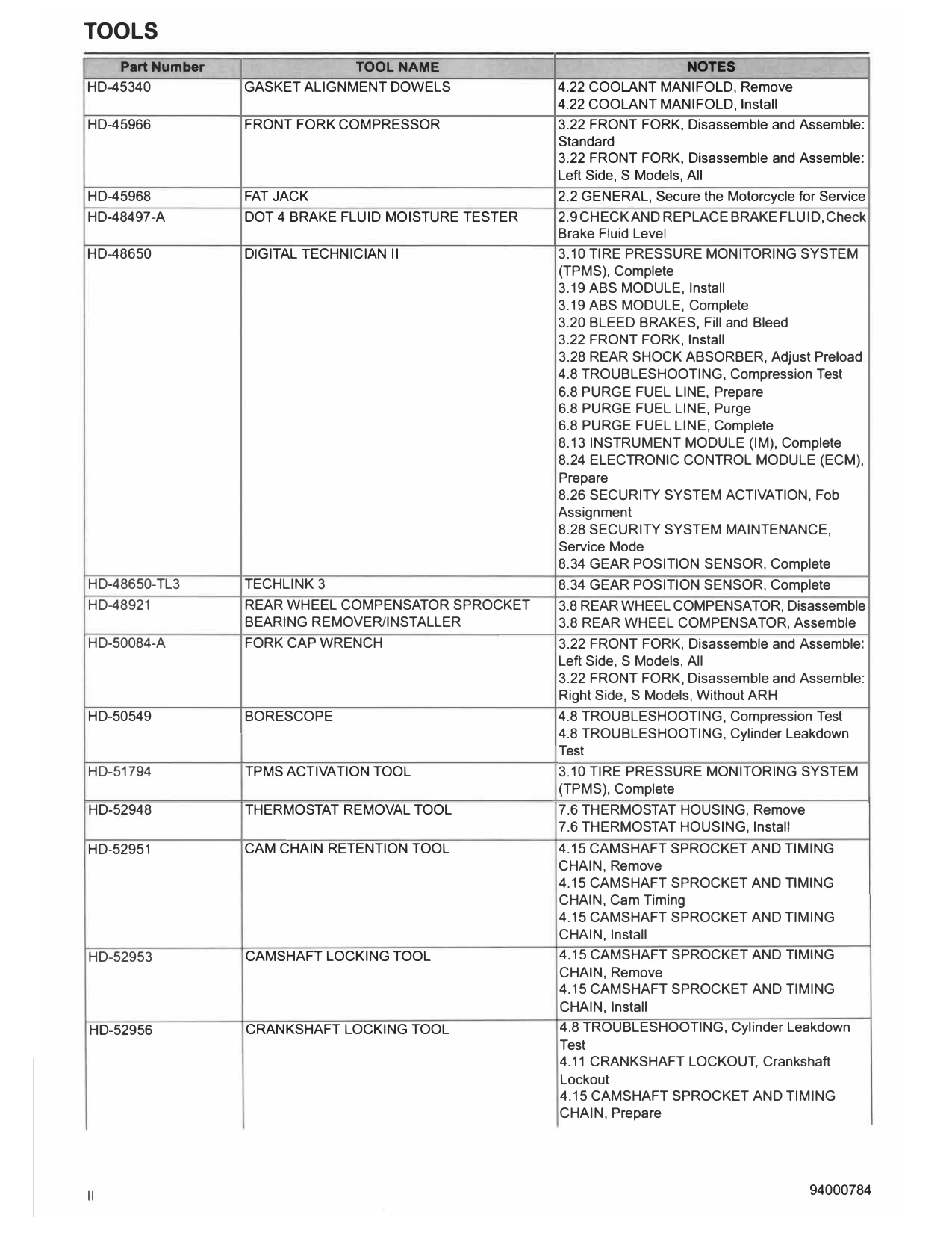
TOOLS
Part Number TOOLNAME NOTES
HD-45340 GASKET ALIGNMENT DOWELS 4.22 COOLANT MANIFOLD, Remove
4.22 COOLANT MANIFOLD, Install
HD-45966 FRONT FORK COMPRESSOR 3.22 FRONT FORK, Disassemble and Assemble:
Standard
3.22 FRONT FORK, Disassemble and Assemble:
Left Side, S Models, All
HD-45968 FAT JACK 2.2 GENERAL, Secure the Motorcycle for Service
HD-48497-A DOT 4 BRAKE FLUID MOISTURE TESTER 2.9 CHECK AND REPLACE BRAKE FLUID, Check
Brake Fluid Level
HD-48650 DIGITAL TECHNICIAN II 3.10 TIRE PRESSURE MONITORING SYSTEM
(TPMS), Complete
3.19 ABS MODULE, Install
3.19 ABS MODULE, Complete
3.20 BLEED BRAKES, Fill and Bleed
3.22 FRONT FORK, Install
3.28 REAR SHOCK ABSORBER, Adjust Preload
4.8 TROUBLESHOOTING, Compression Test
6.8 PURGE FUEL LINE, Prepare
6.8 PURGE FUEL LINE, Purge
6.8 PURGE FUEL LINE, Complete
8.13 INSTRUMENT MODULE (IM), Complete
8.24 ELECTRONIC CONTROL MODULE (ECM),
Prepare
8.26 SECURITY SYSTEM ACTIVATION, Fob
Assignment
8.28 SECURITY SYSTEM MAINTENANCE,
Service Mode
8.34 GEAR POSITION SENSOR, Complete
HD-48650-TL3 TECHLINK 3 8.34 GEAR POSITION SENSOR, Complete
HD-48921 REAR WHEEL COMPENSATOR SPROCKET 3.8 REAR WHEEL COMPENSATOR, Disassemble
BEARING REMOVER/INSTALLER 3.8 REAR WHEEL COMPENSATOR, Assemble
HD-50084-A FORK CAP WRENCH 3.22 FRONT FORK, Disassemble and Assemble:
Left Side, S Models, All
3.22 FRONT FORK, Disassemble and Assemble:
Right Side, S Models, Without ARH
HD-50549 BORESCOPE 4.8 TROUBLESHOOTING, Compression Test
4.8 TROUBLESHOOTING, Cylinder Leakdown
Test
HD-51794 TPMS ACTIVATION TOOL 3.10 TIRE PRESSURE MONITORING SYSTEM
(TPMS), Complete
HD-52948 THERMOSTAT REMOVAL TOOL 7.6 THERMOSTAT HOUSING, Remove
7.6 THERMOSTAT HOUSING, Install
HD-52951 CAM CHAIN RETENTION TOOL 4.15 CAMSHAFT SPROCKET AND TIMING
CHAIN, Remove
4.15 CAMSHAFT SPROCKET AND TIMING
CHAIN, Cam Timing
4.15 CAMSHAFT SPROCKET AND TIMING
CHAIN, Install
HD-52953 CAMSHAFT LOCKING TOOL 4.15 CAMSHAFT SPROCKET AND TIMING
CHAIN, Remove
4.15 CAMSHAFT SPROCKET AND TIMING
CHAIN, Install
HD-52956 CRANKSHAFT LOCKING TOOL 4.8 TROUBLESHOOTING, Cylinder Leakdown
Test
4.11 CRANKSHAFT LOCKOUT, Crankshaft
Lockout
4.15 CAMSHAFT SPROCKET AND TIMING
CHAIN, Prepare
II 94000784
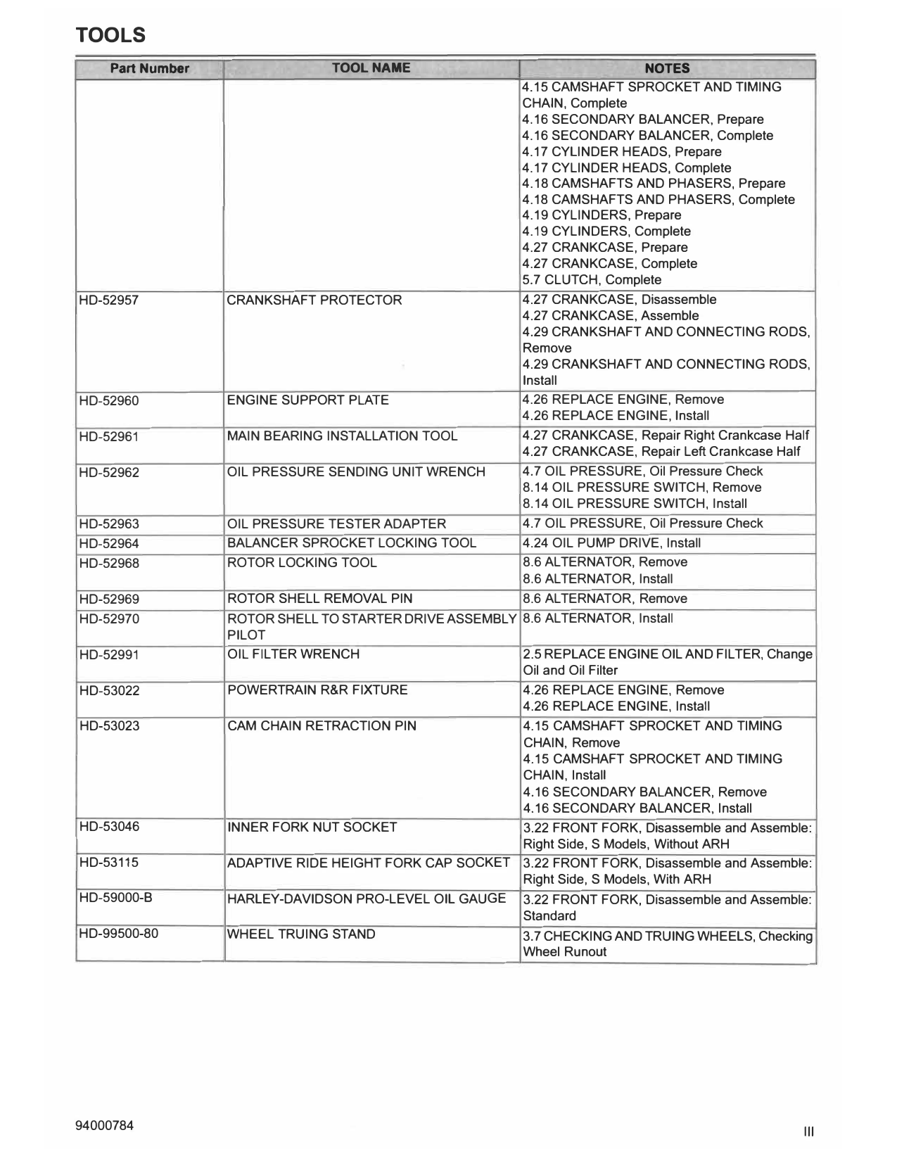
TOOLS
Part Number TOOL NAME NOTES
4.15 CAMSHAFT SPROCKET AND TIMING
CHAIN, Complete
4.16 SECONDARY BALANCER, Prepare
4.16 SECONDARY BALANCER, Complete
4.17 CYLINDER HEADS, Prepare
4.17 CYLINDER HEADS, Complete
4.18 CAMSHAFTS AND PHASERS, Prepare
4.18 CAMSHAFTS AND PHASERS, Complete
4.19 CYLINDERS, Prepare
4.19 CYLINDERS, Complete
4.27 CRANKCASE, Prepare
4.27 CRANKCASE, Complete
5.7 CLUTCH, Complete
HD-52957 CRANKSHAFT PROTECTOR 4.27 CRANKCASE, Disassemble
4.27 CRANKCASE, Assemble
4.29 CRANKSHAFT AND CONNECTING RODS,
Remove
4.29 CRANKSHAFT AND CONNECTING RODS,
Install
HD-52960 ENGINE SUPPORT PLATE 4.26 REPLACE ENGINE, Remove
4.26 REPLACE ENGINE, Install
HD-52961 MAIN BEARING INSTALLATION TOOL 4.27 CRANKCASE, Repair Right Crankcase Half
4.27 CRANKCASE, Repair Left Crankcase Half
HD-52962 OIL PRESSURE SENDING UNIT WRENCH 4.7 OIL PRESSURE, Oil Pressure Check
8.14 OIL PRESSURE SWITCH, Remove
8.14 OIL PRESSURE SWITCH, Install
HD-52963 OIL PRESSURE TESTER ADAPTER 4.7 OIL PRESSURE, Oil Pressure Check
HD-52964 BALANCER SPROCKET LOCKING TOOL 4.24 OIL PUMP DRIVE, Install
HD-52968 ROTOR LOCKING TOOL 8.6 ALTERNATOR, Remove
8.6 ALTERNATOR, Install
HD-52969 ROTOR SHELL REMOVAL PIN 8.6 ALTERNATOR, Remove
HD-52970 ROTOR SHELL TO STARTER DRIVE ASSEMBLY 8.6 ALTERNATOR, Install
PILOT
HD-52991 OIL FILTER WRENCH 2.5 REPLACE ENGINE OIL AND FILTER, Change
Oil and Oil Filter
HD-53022 POWERTRAIN R&R FIXTURE 4.26 REPLACE ENGINE, Remove
4.26 REPLACE ENGINE, Install
HD-53023 CAM CHAIN RETRACTION PIN 4.15 CAMSHAFT SPROCKET AND TIMING
CHAIN, Remove
4.15 CAMSHAFT SPROCKET AND TIMING
CHAIN, Install
4.16 SECONDARY BALANCER, Remove
4.16 SECONDARY BALANCER, Install
HD-53046 INNER FORK NUT SOCKET 3.22 FRONT FORK, Disassemble and Assemble:
Right Side, S Models, Without ARH
HD-53115 ADAPTIVE RIDE HEIGHT FORK CAP SOCKET 3.22 FRONT FORK, Disassemble and Assemble:
Right Side, S Models, With ARH
HD-59000-B HARLEY-DAVIDSON PRO-LEVEL OIL GAUGE 3.22 FRONT FORK, Disassemble and Assemble:
Standard
HD-99500-80 WHEEL TRUING STAND 3.7 CHECKING AND TRUING WHEELS, Checking
Wheel Runout
94000784 Ill
NOTES
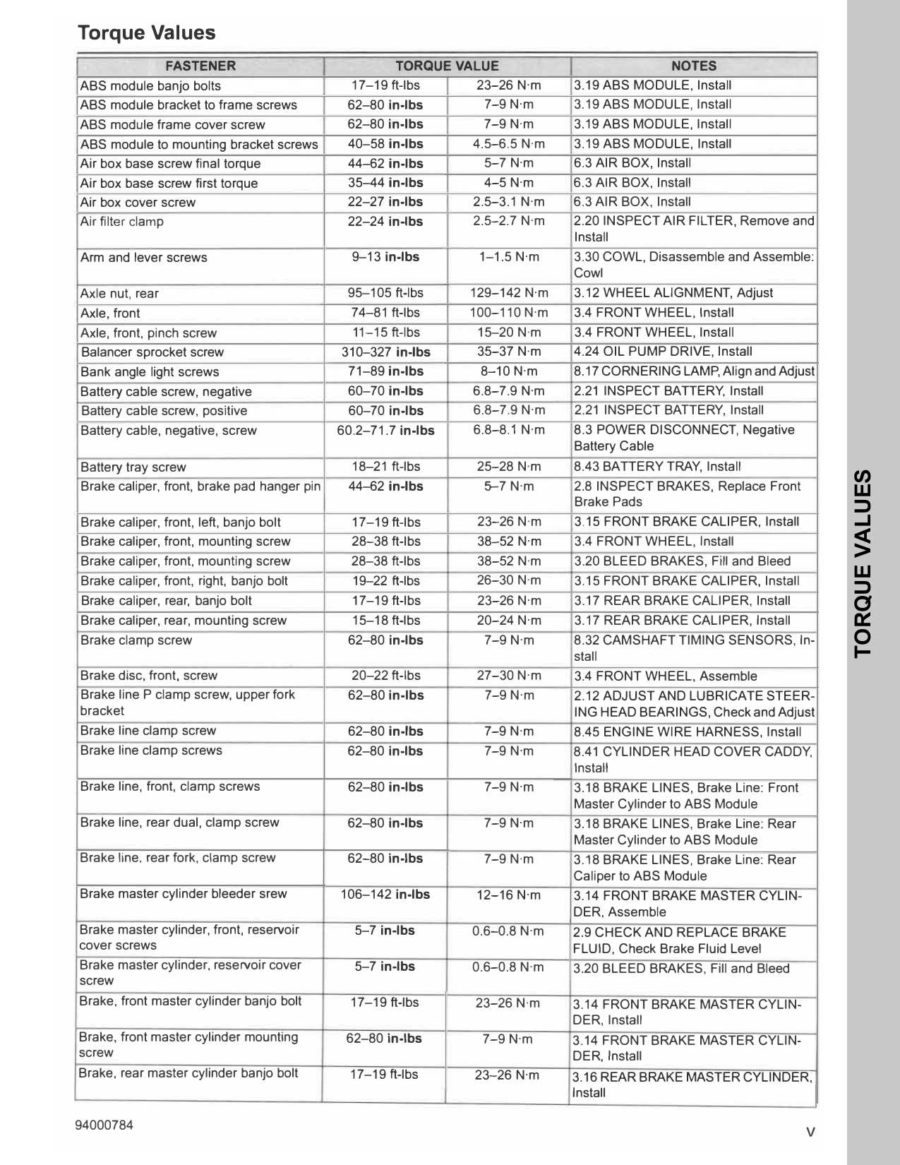
Torque Values
FASTENER TORQUE VALUE NOTES
ABS module banjo bolts 17-19ft-lbs 23-26N·m 3.19ABS MODULE, Install
ABS module bracket to frame screws 62-80 in-lbs 7-9N·m 3.19ABS MODULE, Install
ABS module frame cover screw 62-80 in-lbs 7-9N·m 3.19ABS MODULE, Install
ABS module to mounting bracket screws 40-58 in-lbs 4.5-6.5N·m 3.19ABS MODULE, Install
Air box base screw final torque 44-62 in-lbs 5-7N·m 6.3AIR BOX, Install
Air box base screw first torque 35-44 in-lbs 4-5N·m 6.3AIR BOX, Install
Air box cover screw 22-27 in-lbs 2.5-3.1N·m 6.3AIR BOX, Install
Air filter clamp 22-24 in-lbs 2.5-2.7N·m 2.20INSPECT AIR FILTER, Remove and
Install
Arm and lever screws 9-13 in-lbs 1-1.5N·m 3.30COWL, Disassemble and Assemble:
Cowl
Axle nut, rear 95-105 ft-lbs 129-142N·m 3.12WHEEL ALIGNMENT, Adjust
Axle, front 74-81ft-lbs 100-110N·m 3.4FRONT WHEEL, Install
Axle, front, pinch screw 11-15 ft-lbs 15-20N·m 3.4FRONT WHEEL, Install
Balancer sprocket screw 310-327 in-lbs 35-37N·m 4.24OIL PUMP DRIVE, Install
Bank angle light screws 71-89 in-lbs 8-10N·m 8.17CORNERING LAMP, Align and Adjust
Battery cable screw, negative 60-70 in-lbs 6.8-7.9N·m 2.21INSPECT BATTERY, Install
Battery cable screw, positive 60-70 in-lbs 6.8-7.9N·m 2.21INSPECT BATTERY, Install
Battery cable, negative, screw 60.2-71.7 in-lbs 6.8-8.1 N·m 8.3POWER DISCONNECT, Negative
Battery Cable
Battery tray screw 18-21ft-lbs 25-28N·m 8.43BATTERY TRAY, Install
TORQUE VALUES
Brake caliper, front, brake pad hanger pin 44-62 in-lbs 5-7N·m 2.8INSPECT BRAKES, Replace Front
Brake Pads
Brake caliper, front, left, banjo bolt 17-19ft-lbs 23-26N·m 3.15FRONT BRAKE CALIPER, Install
Brake caliper, front, mounting screw 28-38ft-lbs 38-52N·m 3.4FRONT WHEEL, Install
Brake caliper, front, mounting screw 28-38ft-lbs 38-52N·m 3.20BLEED BRAKES, Fill and Bleed
Brake caliper, front, right, banjo bolt 19-22 ft-lbs 26-30N·m 3.15FRONT BRAKE CALIPER, Install
Brake caliper, rear, banjo bolt 17-19ft-lbs 23-26N·m 3.17REAR BRAKE CALIPER, Install
Brake caliper, rear, mounting screw 15-18ft-lbs 20-24N·m 3.17REAR BRAKE CALIPER, Install
Brake clamp screw 62-80 in-lbs 7-9N·m 8.32CAMSHAFT TIMING SENSORS, In-
stall
Brake disc, front, screw 20-22ft-lbs 27-30N·m 3.4FRONT WHEEL, Assemble
Brake line P clamp screw, upper fork 62-80 in-lbs 7-9N·m 2.12ADJUST AND LUBRICATE STEER-
bracket ING HEAD BEARINGS, Check and Adjust
Brake line clamp screw 62-80 in-lbs 7-9N·m 8.45ENGINE WIRE HARNESS, Install
Brake line clamp screws 62-80 in-lbs 7-9N·m 8.41CYLINDER HEAD COVER CADDY,
Install
Brake line, front, clamp screws 62-80 in-lbs 7-9N·m 3.18BRAKE LINES, Brake Line: Front
Master Cylinder to ABS Module
Brake line, rear dual, clamp screw 62-80 in-lbs 7-9N·m 3.18BRAKE LINES, Brake Line: Rear
Master Cylinder to ABS Module
Brake line, rear fork, clamp screw 62-80 in-lbs 7-9N·m 3.18BRAKE LINES, Brake Line: Rear
Caliper to ABS Module
Brake master cylinder bleeder srew 106-142 in-lbs 12-16N·m 3.14FRONT BRAKE MASTER CYLIN-
DER, Assemble
Brake master cylinder, front, reservoir 5-7 in-lbs 0.6-0.8N·m 2.9CHECK AND REPLACE BRAKE
cover screws FLUID, Check Brake Fluid Level
Brake master cylinder, reservoir cover 5-7 in-lbs 0.6-0.8N·m 3.20BLEED BRAKES, Fill and Bleed
screw
Brake, front master cylinder banjo bolt 17-19ft-lbs 23-26N·m 3.14FRONT BRAKE MASTER CYLIN-
DER, Install
Brake, front master cylinder mounting 62-80 in-lbs 7-9N·m 3.14FRONT BRAKE MASTER CYLIN-
screw DER, Install
Brake, rear master cylinder banjo bolt 17-19ft-lbs 23-26N·m 3.16REAR BRAKE MASTER CYLINDER,
Install
V
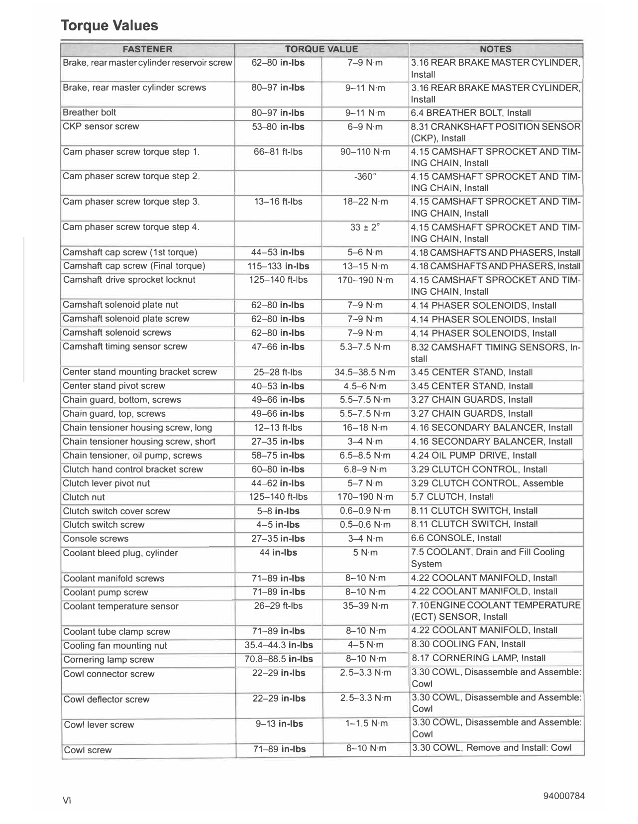
Torque Values
FASTENER TORQUE VALUE NOTES
Brake, rear master cylinder reservoir screw 62-80 in-lbs 7-9 N·m 3.16 REAR BRAKE MASTER CYLINDER,
Install
Brake, rear master cylinder screws 80-97 in-lbs 9-11 N·m 3.16 REAR BRAKE MASTER CYLINDER,
Install
Breather bolt 80-97 in-lbs 9-11 N·m 6.4 BREATHER BOLT, Install
CKP sensor screw 53-80 in-lbs 6-9 N·m 8.31 CRANKSHAFT POSITION SENSOR
(CKP), Install
Cam phaser screw torque step 1. 66-81 ft-lbs 90-110 N·m 4.15 CAMSHAFT SPROCKET AND TIM-
ING CHAIN, Install
Cam phaser screw torque step 2. -360 ° 4.15 CAMSHAFT SPROCKET AND TIM-
ING CHAIN, Install
Cam phaser screw torque step 3. 13-16 ft-lbs 18-22 N·m 4.15 CAMSHAFT SPROCKET AND TIM-
ING CHAIN, Install
Cam phaser screw torque step 4. 33 ± 2° 4.15 CAMSHAFT SPROCKET AND TIM-
ING CHAIN, Install
Camshaft cap screw (1st torque) 44-53 in-lbs 5-6 N·m 4.18 CAMSHAFTS AND PHASERS, Install
Camshaft cap screw (Final torque) 115-133 in-lbs 13-15 N·m 4.18 CAMSHAFTS AND PHASERS, Install
Camshaft drive sprocket locknut 125-140 ft-lbs 170-190 N·m 4.15 CAMSHAFT SPROCKET AND TIM-
ING CHAIN, Install
Camshaft solenoid plate nut 62-80 in-lbs 7-9 N·m 4.14 PHASER SOLENOIDS, Install
Camshaft solenoid plate screw 62-80 in-lbs 7-9 N·m 4.14 PHASER SOLENOIDS, Install
Camshaft solenoid screws 62-80 in-lbs 7-9 N·m 4.14 PHASER SOLENOIDS, Install
Camshaft timing sensor screw 47-66 in-lbs 5.3-7.5 N·m 8.32 CAMSHAFT TIMING SENSORS, In-
stall
Center stand mounting bracket screw 25-28 ft-lbs 34.5-38.5 N·m 3.45 CENTER STAND, Install
Center stand pivot screw 40-53 in-lbs 4.5-6 N·m 3.45 CENTER STAND, Install
Chain guard, bottom, screws 49-66 in-lbs 5.5-7.5 N·m 3.27 CHAIN GUARDS, Install
Chain guard, top, screws 49-66 in-lbs 5.5-7.5 N·m 3.27 CHAIN GUARDS, Install
Chain tensioner housing screw, long 12-13 ft-lbs 16-18 N·m 4.16 SECONDARY BALANCER, Install
Chain tensioner housing screw, short 27-35 in-lbs 3--4 N·m 4.16 SECONDARY BALANCER, Install
Chain tensioner, oil pump, screws 58-75 in-lbs 6.5-8.5 N·m 4.24 OIL PUMP DRIVE, Install
Clutch hand control bracket screw 60-80 in-lbs 6.8-9 N·m 3.29 CLUTCH CONTROL, Install
Clutch lever pivot nut 44-62 in-lbs 5-7 N·m 3.29 CLUTCH CONTROL, Assemble
Clutch nut 125-140 ft-lbs 170-190 N·m 5.7 CLUTCH, Install
Clutch switch cover screw 5-8 in-lbs 0.6-0.9 N·m 8.11 CLUTCH SWITCH, Install
Clutch switch screw 4-5 in-lbs 0.5-0.6 N·m 8.11 CLUTCH SWITCH, Install
Console screws 27-35 in-lbs 3--4 N·m 6.6 CONSOLE, Install
Coolant bleed plug, cylinder 44 in-lbs 5 N·m 7.5 COOLANT, Drain and Fill Cooling
System
Coolant manifold screws 71-89 in-lbs 8-10 N·m 4.22 COOLANT MANIFOLD, Install
Coolant pump screw 71-89 in-lbs 8-10 N·m 4.22 COOLANT MANIFOLD, Install
Coolant temperature sensor 26-29 ft-lbs 35-39 N·m 7.10 ENGINE COOLANT TEMPERATURE
(ECT) SENSOR, Install
Coolant tube clamp screw 71-89 in-lbs 8-10 N·m 4.22 COOLANT MANIFOLD, Install
Cooling fan mounting nut 35.4--44.3 in-lbs 4-5 N·m 8.30 COOLING FAN, Install
Cornering lamp screw 70.8-88.5 in-lbs 8-10 N·m 8.17 CORNERING LAMP, Install
Cowl connector screw 22-29 in-lbs 2.5-3.3 N·m 3.30 COWL, Disassemble and Assemble:
Cowl
Cowl deflector screw 22-29 in-lbs 2.5-3.3 N·m 3.30 COWL, Disassemble and Assemble:
Cowl
Cowl lever screw 9-13 in-lbs 1-1.5 N·m 3.30 COWL, Disassemble and Assemble:
Cowl
Cowl screw 71-89 in-lbs 8-10 N·m 3.30 COWL, Remove and Install: Cowl
VI 94000784
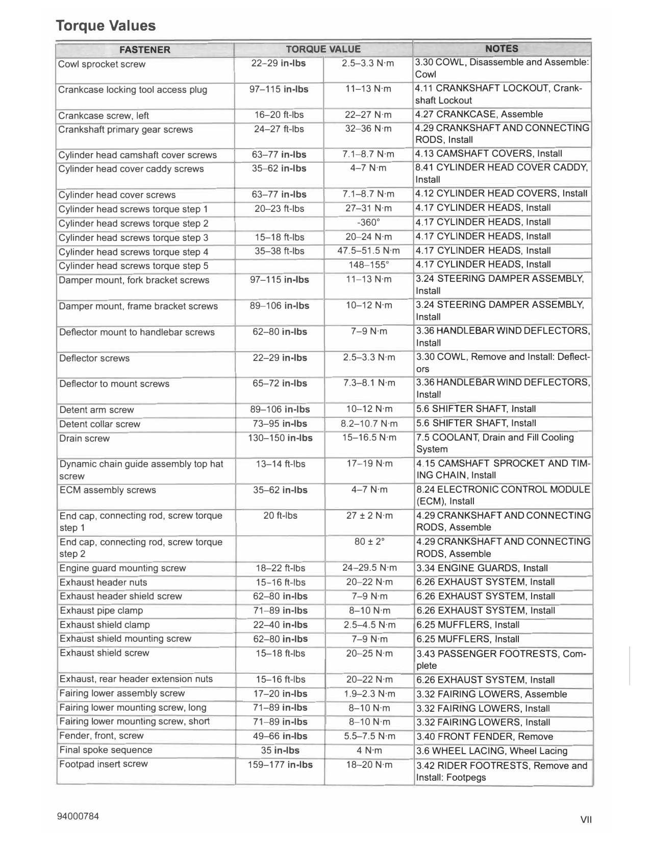
Torque Values
FASTENER TORQUE VALUE NOTES
Cowl sprocket screw 22-29 in-lbs 2.5-3.3 N·m 3.30 COWL, Disassemble and Assemble:
Cowl
Crankcase locking tool access plug 97-115 in-lbs 11-13 N·m 4.11 CRANKSHAFT LOCKOUT, Crank-
shaft Lockout
Crankcase screw, left 16-20 ft-lbs 22-27 N·m 4.27 CRANKCASE, Assemble
Crankshaft primary gear screws 24-27 ft-lbs 32-36 N·m 4.29 CRANKSHAFT AND CONNECTING
RODS, Install
Cylinder head camshaft cover screws 63-77 in-lbs 7.1-8.7 N·m 4.13 CAMSHAFT COVERS, Install
Cylinder head cover caddy screws 35-62 in-lbs 4-7 N·m 8.41 CYLINDER HEAD COVER CADDY,
Install
Cylinder head cover screws 63-77 in-lbs 7.1-8.7 N·m 4.12 CYLINDER HEAD COVERS, Install
Cylinder head screws torque step 1 20-23 ft-lbs 27-31 N·m 4.17 CYLINDER HEADS, Install
Cylinder head screws torque step 2 -360 ° 4.17 CYLINDER HEADS, Install
Cylinder head screws torque step 3 15-18 ft-lbs 20-24 N·m 4.17 CYLINDER HEADS, Install
Cylinder head screws torque step 4 35-38 ft-lbs 47.5-51.5 N·m 4.17 CYLINDER HEADS, Install
Cylinder head screws torque step 5 148-155 ° 4.17 CYLINDER HEADS, Install
Damper mount, fork bracket screws 97-115 in-lbs 11-13 N·m 3.24 STEERING DAMPER ASSEMBLY,
Install
Damper mount, frame bracket screws 89-106 in-lbs 10-12 N·m 3.24 STEERING DAMPER ASSEMBLY,
Install
Deflector mount to handlebar screws 62-80 in-lbs 7-9 N·m 3.36 HANDLEBAR WIND DEFLECTORS,
Install
Deflector screws 22-29 in-lbs 2.5-3.3 N·m 3.30 COWL, Remove and Install: Deflect-
ors
Deflector to mount screws 65-72 in-lbs 7.3-8.1 N·m 3.36 HANDLEBAR WIND DEFLECTORS,
Install
Detent arm screw 89-106 in-lbs 10-12 N·m 5.6 SHIFTER SHAFT, Install
Detent collar screw 73-95 in-lbs 8.2-10.7 N·m 5.6 SHIFTER SHAFT, Install
Drain screw 130-150 in-lbs 15-16.5 N·m 7.5 COOLANT, Drain and Fill Cooling
System
Dynamic chain guide assembly top hat 13-14 ft-lbs 17-19 N·m 4.15 CAMSHAFT SPROCKET AND TIM-
screw ING CHAIN, Install
ECM assembly screws 35-62 in-lbs 4-7 N·m 8.24 ELECTRONIC CONTROL MODULE
(ECM), Install
End cap, connecting rod, screw torque 20 ft-lbs 27 ± 2 N·m 4.29 CRANKSHAFT AND CONNECTING
step 1 RODS, Assemble
End cap, connecting rod, screw torque 80 ± 2 ° 4.29 CRANKSHAFT AND CONNECTING
step 2 RODS, Assemble
Engine guard mounting screw 18-22 ft-lbs 24-29.5 N·m 3.34 ENGINE GUARDS, Install
Exhaust header nuts 15-16 ft-lbs 20-22 N·m 6.26 EXHAUST SYSTEM, Install
Exhaust header shield screw 62-80 in-lbs 7-9 N·m 6.26 EXHAUST SYSTEM, Install
Exhaust pipe clamp 71-89 in-lbs 8-10 N·m 6.26 EXHAUST SYSTEM, Install
Exhaust shield clamp 22-40 in-lbs 2.5-4.5 N·m 6.25 MUFFLERS, Install
Exhaust shield mounting screw 62-80 in-lbs 7-9 N·m 6.25 MUFFLERS, Install
Exhaust shield screw 15-18 ft-lbs 20-25 N·m 3.43 PASSENGER FOOTRESTS, Com-
plete
Exhaust, rear header extension nuts 15-16 ft-lbs 20-22 N·m 6.26 EXHAUST SYSTEM, Install
Fairing lower assembly screw 17-20 in-lbs 1.9-2.3 N·m 3.32 FAIRING LOWERS, Assemble
Fairing lower mounting screw, long 71-89 in-lbs 8-10 N·m 3.32 FAIRING LOWERS, Install
Fairing lower mounting screw, short 71-89 in-lbs 8-10 N·m 3.32 FAIRING LOWERS, Install
Fender, front, screw 49--66 in-lbs 5.5-7.5 N·m 3.40 FRONT FENDER, Remove
Final spoke sequence 35 in-lbs 4 N·m 3.6 WHEEL LACING, Wheel Lacing
Footpad insert screw 159-177 in-lbs 18-20 N·m 3.42 RIDER FOOTRESTS, Remove and
Install: Footpegs
94000784 VII
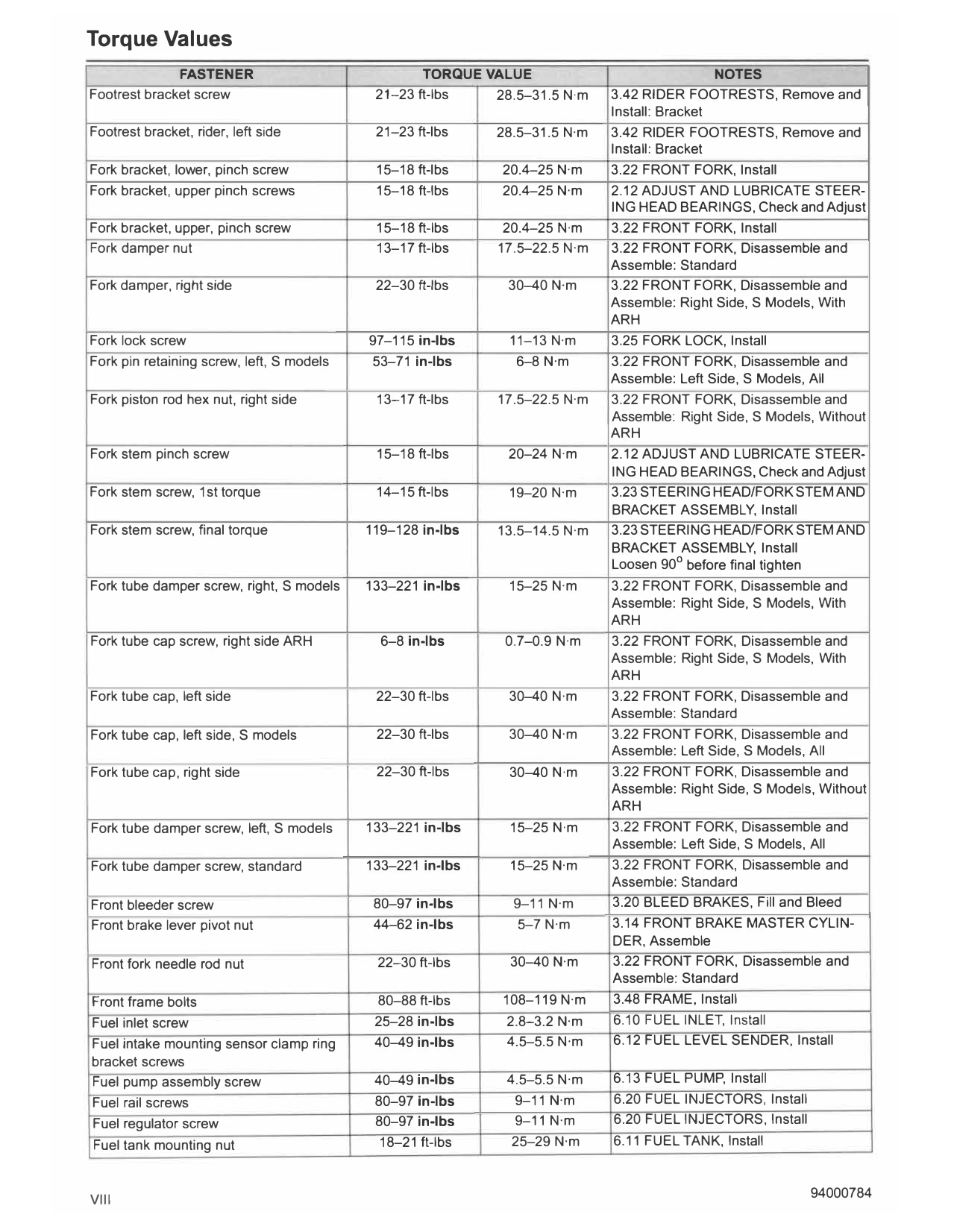
Torque Values
FASTENER TORQUE VALUE NOTES
Footrest bracket screw 21-23 ft-lbs 28.5-31.5 N·m 3.42 RIDER FOOTRESTS, Remove and
Install: Bracket
Footrest bracket, rider, left side 21-23 ft-lbs 28.5-31.5 N·m 3.42 RIDER FOOTRESTS, Remove and
Install: Bracket
Fork bracket, lower, pinch screw 15-18 ft-lbs 20.4-25 N·m 3.22 FRONT FORK, Install
Fork bracket, upper pinch screws 15-18 ft-lbs 20.4-25 N·m 2.12 ADJUST AND LUBRICATE STEER-
ING HEAD BEARINGS, Check and Adjust
Fork bracket, upper, pinch screw 15-18 ft-lbs 20.4-25 N·m 3.22 FRONT FORK, Install
Fork damper nut 13-17 ft-lbs 17.5-22.5 N·m 3.22 FRONT FORK, Disassemble and
Assemble: Standard
Fork damper, right side 22-30 ft-lbs 30-40 N·m 3.22 FRONT FORK, Disassemble and
Assemble: Right Side, S Models, With
ARH
Fork lock screw 97-115 in-lbs 11-13 N·m 3.25 FORK LOCK, Install
Fork pin retaining screw, left, S models 53-71 in-lbs 6-8 N·m 3.22 FRONT FORK, Disassemble and
Assemble: Left Side, S Models, All
Fork piston rod hex nut, right side 13-17 ft-lbs 17.5-22.5 N·m 3.22 FRONT FORK, Disassemble and
Assemble: Right Side, S Models, Without
ARH
Fork stem pinch screw 15-18 ft-lbs 20-24 N·m 2.12 ADJUST AND LUBRICATE STEER-
ING HEAD BEARINGS, Check and Adjust
Fork stem screw, 1st torque 14-15 ft-lbs 19-20 N·m 3.23 STEERING HEAD/FORK STEM AND
BRACKET ASSEMBLY, Install
Fork stem screw, final torque 119-128 in-lbs 13.5-14.5 N·m 3.23 STEERING HEAD/FORK STEM AND
BRACKET ASSEMBLY, Install
°
Loosen 90 before final tighten
Fork tube damper screw, right, S models 133-221 in-lbs 15-25 N·m 3.22 FRONT FORK, Disassemble and
Assemble: Right Side, S Models, With
ARH
Fork tube cap screw, right side ARH 6-8 in-lbs 0.7-0.9 N·m 3.22 FRONT FORK, Disassemble and
Assemble: Right Side, S Models. With
ARH
Fork tube cap, left side 22-30 ft-lbs 30-40 N·m 3.22 FRONT FORK, Disassemble and
Assemble: Standard
Fork tube cap, left side, S models 22-30 ft-lbs 30-40 N·m 3.22 FRONT FORK, Disassemble and
Assemble: Left Side, S Models, All
Fork tube cap, right side 22-30 ft-lbs 30-40 N·m 3.22 FRONT FORK, Disassemble and
Assemble: Right Side, S Models, Without
ARH
Fork tube damper screw, left, S models 133-221 in-lbs 15-25 N·m 3.22 FRONT FORK, Disassemble and
Assemble: Left Side, S Models, All
Fork tube damper screw, standard 133-221 in-lbs 15-25 N·m 3.22 FRONT FORK, Disassemble and
Assemble: Standard
Front bleeder screw 80-97 in-lbs 9-11 N·m 3.20 BLEED BRAKES, Fill and Bleed
Front brake lever pivot nut 44-62 in-lbs 5-7 N·m 3.14 FRONT BRAKE MASTER CYLIN-
DER, Assemble
Front fork needle rod nut 22-30 ft-lbs 30-40 N·m 3.22 FRONT FORK, Disassemble and
Assemble: Standard
Front frame bolts 80-88 ft-lbs 108-119 N·m 3.48 FRAME, Install
Fuel inlet screw 25-28 in-lbs 2.8-3.2 N·m 6.10 FUEL INLET, Install
Fuel intake mounting sensor clamp ring 40-49 in-lbs 4.5-5.5 N·m 6.12 FUEL LEVEL SENDER, Install
bracket screws
Fuel pump assembly screw 40-49 in-lbs 4.5-5.5 N·m 6.13 FUEL P UMP, Install
Fuel rail screws 80-97 in-lbs 9-11 N·m 6.20 FUEL INJECTORS, Install
Fuel regulator screw 80-97 in-lbs 9-11 N·m 6.20 FUEL INJECTORS, Install
Fuel tank mounting nut 18-21 ft-lbs 25-29 N·m 6.11 FUEL TANK, Install
VIII 94000784
Torque Values
FASTENER TORQUE VALUE NOTES
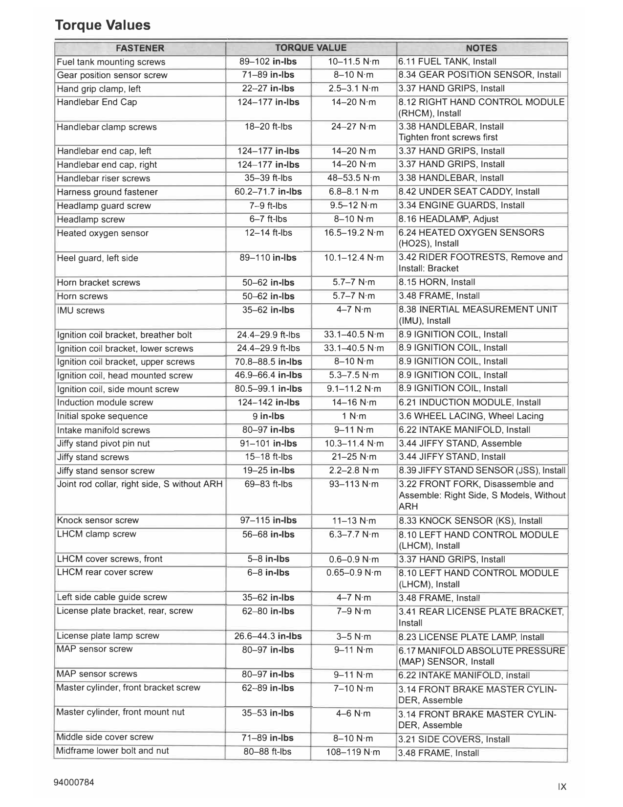
Fuel tank mounting screws 89-102 in-lbs 10-11.5 N·m 6.11 FUEL TANK, Install
Gear position sensor screw 71-89 in-lbs 8-10 N·m 8.34 GEAR POSITION SENSOR, Install
Hand grip clamp, left 22-27 in-lbs 2.5-3.1 N·m 3.37 HAND GRIPS, Install
Handlebar End Cap 124-177 in-lbs 14-20 N·m 8.12 RIGHT HAND CONTROL MODULE
(RHCM), Install
Handlebar clamp screws 18-20 ft-lbs 24-27 N·m 3.38 HANDLEBAR, Install
Tighten front screws first
Handlebar end cap, left 124-177 in-lbs 14-20 N·m 3.37 HAND GRIPS, Install
Handlebar end cap, right 124-177 in-lbs 14-20 N·m 3.37 HAND GRIPS, Install
Handlebar riser screws 35-39 ft-lbs 48-53.5 N·m 3.38 HANDLEBAR, Install
Harness ground fastener 60.2-71.7 in-lbs 6.8-8.1 N·m 8.42 UNDER SEAT CADDY, Install
Headlamp guard screw 7-9 ft-lbs 9.5--12 N·m 3.34 ENGINE GUARDS, Install
Headlamp screw 6-7 ft-lbs 8-10 N·m 8.16 HEADLAMP, Adjust
Heated oxygen sensor 12-14 ft-lbs 16.5-19.2 N·m 6.24 HEATED OXYGEN SENSORS
(HO2S), Install
Heel guard, left side 89-110 in-lbs 10.1-12.4 N·m 3.42 RIDER FOOTRESTS, Remove and
Install: Bracket
Horn bracket screws 50-62 in-lbs 5.7-7 N·m 8.15 HORN, Install
Horn screws 50-62 in-lbs 5.7-7 N·m 3.48 FRAME, Install
IMU screws 35-62 in-lbs 4-7 N·m 8.38 INERTIAL MEASUREMENT UNIT
(IMU), Install
Ignition coil bracket, breather bolt 24.4-29.9 ft-lbs 33.1-40.5 N·m 8.9 IGNITION COIL, Install
Ignition coil bracket, lower screws 24.4-29.9 ft-lbs 33.1-40.5 N·m 8.9 IGNITION COIL, Install
Ignition coil bracket, upper screws 70.8-88.5 in-lbs 8-10 N·m 8.9 IGNITION COIL, Install
Ignition coil, head mounted screw 46.9-66.4 in-lbs 5.3-7.5 N·m 8.9 IGNITION COIL, Install
Ignition coil, side mount screw 80.5--99.1 in-lbs 9.1-11.2 N·m 8.9 IGNITION COIL, Install
Induction module screw 124-142 in-lbs 14-16 N·m 6.21 INDUCTION MODULE, Install
Initial spoke sequence 9 in-lbs 1 N·m 3.6 WHEEL LACING, Wheel Lacing
Intake manifold screws 80-97 in-lbs 9-11 N·m 6.22 INTAKE MANIFOLD, Install
Jiffy stand pivot pin nut 91-101 in-lbs 10.3-11.4 N·m 3.44 JIFFY STAND, Assemble
Jiffy stand screws 15-18 ft-lbs 21-25 N·m 3.44 JIFFY STAND, Install
Jiffy stand sensor screw 19-25 in-lbs 2.2-2.8 N·m 8.39 JIFFY STAND SENSOR (JSS), Install
Joint rod collar, right side, S without ARH 69-83 ft-lbs 93-113 N·m 3.22 FRONT FORK, Disassemble and
Assemble: Right Side, S Models, Without
ARH
Knock sensor screw 97-115 in-lbs 11-13 N·m 8.33 KNOCK SENSOR (KS), Install
LHCM clamp screw 56-68 in-lbs 6.3-7.7 N·m 8.10 LEFT HAND CONTROL MODULE
(LHCM), Install
LHCM cover screws, front 5--8 in-lbs 0.6-0.9 N·m 3.37 HAND GRIPS, Install
LHCM rear cover screw 6-8 in-lbs 0.65-0.9 N·m 8.10 LEFT HAND CONTROL MODULE
(LHCM), Install
Left side cable guide screw 35-62 in-lbs 4-7 N·m 3.48 FRAME, Install
License plate bracket, rear, screw 62-80 in-lbs 7-9 N·m 3.41 REAR LICENSE PLATE BRACKET,
Install
License plate lamp screw 26.6-44.3 in-lbs 3-5 N·m 8.23 LICENSE PLATE LAMP, Install
MAP sensor screw 80-97 in-lbs 9-11 N·m 6.17 MANIFOLD ABSOLUTE PRESSURE
(MAP) SENSOR, Install
MAP sensor screws 80-97 in-lbs 9-11 N·m 6.22 INTAKE MANIFOLD, Install
Master cylinder, front bracket screw 62-89 in-lbs 7-10 N·m 3.14 FRONT BRAKE MASTER CYLIN-
DER, Assemble
Master cylinder, front mount nut 35-53 in-lbs 4-6 N·m 3.14 FRONT BRAKE MASTER CYLIN-
DER, Assemble
Middle side cover screw 71-89 in-lbs 8-10 N·m 3.21 SIDE COVERS, Install
Midframe lower bolt and nut 80-88 ft-lbs 108-119 N·m 3.48 FRAME, Install
94000784 IX
Torque Values
FASTENER TORQUE VALUE NOTES
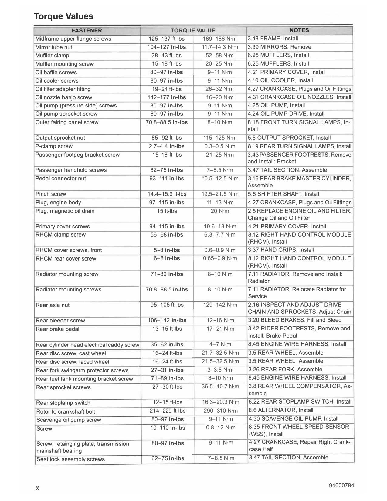
Midframe upper flange screws 125-137 ft-lbs 169-186 N·m 3.48 FRAME, Install
Mirror tube nut 104-127 in-lbs 11.7-14.3 N·m 3.39 MIRRORS, Remove
Muffler clamp 38-43 ft-lbs 52-58 N·m 6.25 MUFFLERS, Install
Muffler mounting screw 15-18 ft-lbs 20-25 N·m 6.25 MUFFLERS, Install
Oil baffle screws 80-97 in-lbs 9-11 N·m 4.21 PRIMARY COVER, Install
Oil cooler screws 80-97 in-lbs 9-11 N·m 4.10 OIL COOLER, Install
Oil filter adapter fitting 19-24 ft-lbs 26-32 N·m 4.27 CRANKCASE, Plugs and Oil Fittings
Oil nozzle banjo screw 142-177 in-lbs 16-20 N·m 4.31 CRANKCASE OIL NOZZLES, Install
Oil pump (pressure side) screws 80-97 in-lbs 9-11 N·m 4.25 OIL PUMP, Install
Oil pump sprocket screw 80-97 in-lbs 9-11 N·m 4.24 OIL PUMP DRIVE, Install
Outer fairing panel screw 70.8-88.5 in-lbs 8-10 N·m 8.18 FRONT TURN SIGNAL LAMPS, In-
stall
Output sprocket nut 85-92 ft-lbs 115-125 N·m 5.5 OUTPUT SPROCKET, Install
P-clamp screw 2.7-4.4 in-lbs 0.3-0.5 N·m 8.19 REAR TURN SIGNAL LAMPS, Install
Passenger footpeg bracket screw 15-18 ft-lbs 21-25 N·m 3.43 PASSENGER FOOTRESTS, Remove
and Install: Bracket
Passenger handhold screws 62-75 in-lbs 7-8.5 N·m 3.47 TAIL SECTION, Assemble
Pedal connector nut 93-111 in-lbs 10.5-12.5 N·m 3.16 REAR BRAKE MASTER CYLINDER,
Assemble
Pinch screw 14.4-15.9 ft-lbs 19.5-2 1.5 N·m 5.6 SHIFTER SHAFT, Install
Plug, engine body 97-115 in-lbs 11-13 N·m 4.27 CRANKCASE , Plugs and Oil Fittings
Plug, magnetic oil drain 15 ft-lbs 20 N·m 2.5 REPLACE ENGINE OIL AND FILTER,
Change Oil and Oil Filter
Primary cover screws 94-115 in-lbs 10.6-13 N·m 4.21 PRIMARY COVER , Install
RHCM clamp screw 56-68 in-lbs 6.3-7.7 N·m 8.12 RIGHT HAND CONTROL MODULE
(RHCM), Install
RHCM cover screws, front 5-8 in-lbs 0.6-0.9 N·m 3.37 HAND GRIPS, Install
RHCM rear cover screw 6-8 in-lbs 0.65-0.9 N·m 8.12 RIGHT HAND CONTROL MODULE
(RHCM), Install
Radiator mounting screw 71-89 in-lbs 8-10 N·m 7.11 RADIATOR, Remove and Install:
Radiator
Radiator mounting screws 70.8-88.5 in-lbs 8-10 N·m 7 .11 RADIATOR, Relocate Radiator for
Service
Rear axle nut 95-105 ft-lbs 129-142 N·m 2.16 INSPECT AND ADJUST DRIVE
CHAIN AND SPROCKETS, Adjust Chain
Rear bleeder screw 106-142 in-lbs 12-16 N·m 3.20 BLEED BRAKES, Fill and Bleed
Rear brake pedal 13-15 ft-lbs 17-21 N·m 3.42 RIDER FOOTRESTS, Remove and
Install: Brake Pedal
Rear cylinder head electrical caddy screw 35-62 in-lbs 4-7 N·m 8.45 ENGINE WIRE HARNESS, Install
Rear disc screw, cast wheel 16-24 ft-lbs 21.7-32.5 N·m 3.5 REAR WHEEL, Assemble
Rear disc screw, laced wheel 16-24 ft-lbs 21.5-32.5 N·m 3.5 REAR WHEEL, Assemble
Rear fork swingarm protector screws 27-31 in-lbs 3-3.5 N·m 3.26 REAR FORK, Assemble
Rear fuel tank mounting bracket screw 71-89 in-lbs 8-10 N·m 8.45 ENGINE WIRE HARNESS, Install
Rear sprocket screws 27-30 ft-lbs 36.5-40.7 N·m 3.8 REAR WHEEL COMPENSATOR, As-
semble
Rear stoplamp switch 12-15 ft-lbs 16.3-20.3 N·m 8.22 REAR STOPLAMP SWITCH, Install
Rotor to crankshaft bolt 214-229 ft-lbs 290-310 N·m 8.6 ALTERNATOR, Install
Scavenge oil pump screw 80-97 in-lbs 9-11 N·m 4.30 SCAVENGE OIL PUMP, Install
Screw 10-110 in-lbs 0.8-12 N·m 8.35 FRONT WHEEL SPEED SENSOR
(WSS), Install
Screw, retainging plate, transmission 80-97 in-lbs 9-11 N·m 4.27 CRANKCASE, Repair Right Crank-
mainshaft bearing case Half
Seat lock assembly screws 62-75 in-lbs 7-8.5 N·m 3.47 TAIL SECTION, Assemble
X
Torque Values
FASTENER TORQUE VALUE NOTES
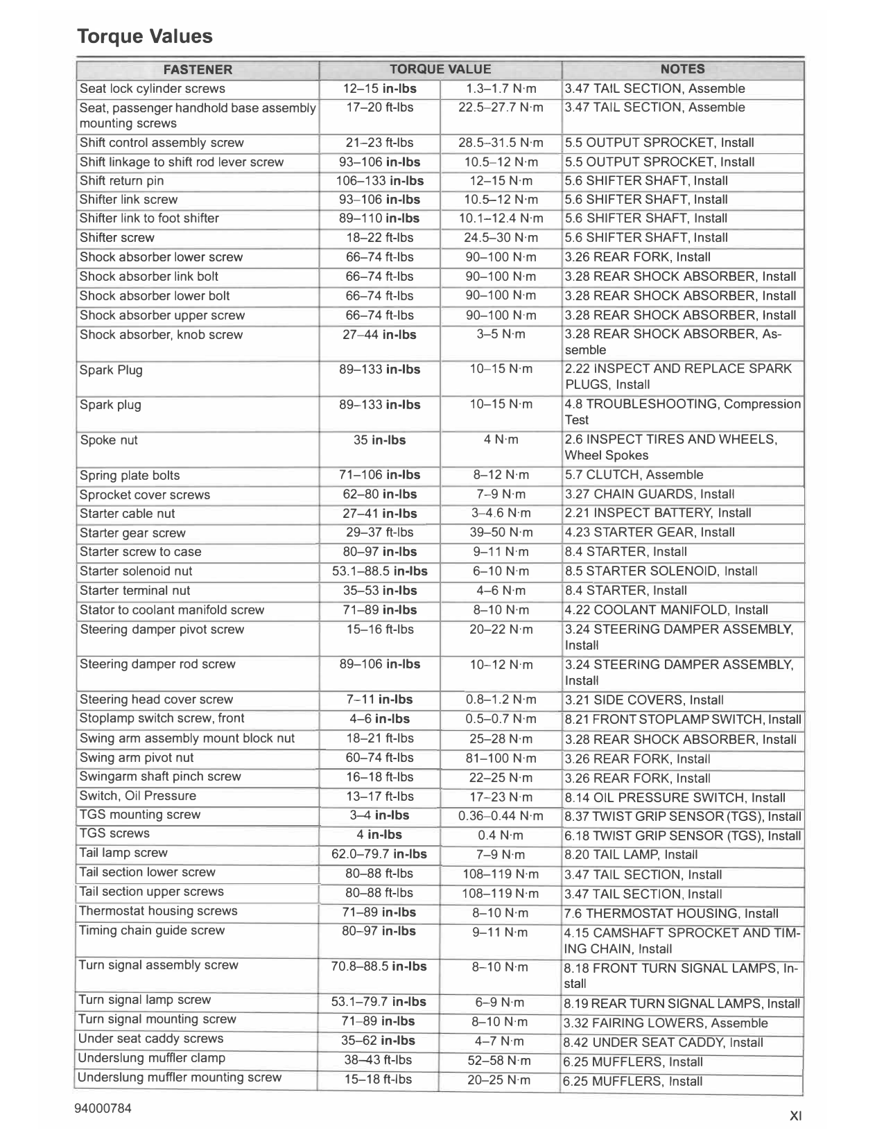
Seat lock cylinder screws 12-15 in-lbs 1.3-1.7 N·m 3.47 TAIL SECTION, Assemble
Seat, passenger handhold base assembly 17-20 ft-lbs 22.5-27.7 N·m 3.47 TAIL SECTION, Assemble
mounting screws
Shift control assembly screw 21-23 ft-lbs 28.5-31.5 N·m 5.5 OUTPUT SPROCKET, Install
Shift linkage to shift rod lever screw 93-106 in-lbs 10.5-12 N·m 5.5 OUTPUT SPROCKET, Install
Shift return pin 106-133 in-lbs 12-15 N·m 5.6 SHIFTER SHAFT, Install
Shifter link screw 93-106 in-lbs 10.5-12 N·m 5.6 SHIFTER SHAFT, Install
Shifter link to foot shifter 89-110 in-lbs 10.1-12.4 N·m 5.6 SHIFTER SHAFT, Install
Shifter screw 18-22 ft-lbs 24.5-30 N·m 5.6 SHIFTER SHAFT, Install
Shock absorber lower screw 66-74 ft-lbs 90-100 N·m 3.26 REAR FORK, Install
Shock absorber link bolt 66-74 ft-lbs 90-100 N·m 3.28 REAR SHOCK ABSORBER, Install
Shock absorber lower bolt 66-74 ft-lbs 90-100 N·m 3.28 REAR SHOCK ABSORBER, Install
Shock absorber upper screw 66-74 ft-lbs 90-100 N·m 3.28 REAR SHOCK ABSORBER, Install
Shock absorber, knob screw 27-44 in-lbs 3-5 N·m 3.28 REAR SHOCK ABSORBER, As-
semble
Spark Plug 89-133 in-lbs 10-15 N·m 2.22 INSPECT AND REPLACE SPARK
PLUGS, Install
Spark plug 89-133 in-lbs 10-15 N·m 4.8 TROUBLESHOOTING, Compression
Test
Spoke nut 35 in-lbs 4 N·m 2.6 INSPECT TIRES AND WHEELS,
Wheel Spokes
Spring plate bolts 71-106 in-lbs 8-12 N·m 5.7 CLUTCH, Assemble
Sprocket cover screws 62-80 in-lbs 7-9 N·m 3.27 CHAIN GUARDS, Install
Starter cable nut 27-41 in-lbs 3-4.6 N·m 2.21 INSPECT BATTERY, Install
Starter gear screw 29-37 ft-lbs 39-50 N·m 4.23 STARTER GEAR, Install
Starter screw to case 80-97 in-lbs 9-11 N·m 8.4 STARTER, Install
Starter solenoid nut 53.1-88.5 in-lbs 6-10 N·m 8.5 STARTER SOLENOID, Install
Starter terminal nut 35-53 in-lbs 4-6 N·m 8.4 STARTER, Install
Stator to coolant manifold screw 71-89 in-lbs 8-10 N·m 4.22 COOLANT MANIFOLD, Install
Steering damper pivot screw 15-16 ft-lbs 20-22 N·m 3.24 STEERING DAMPER ASSEMBLY,
Install
Steering damper rod screw 89-106 in-lbs 10-12 N·m 3.24 STEERING DAMPER ASSEMBLY,
Install
Steering head cover screw 7-11 in-lbs 0.8-1.2 N·m 3.21 SIDE COVERS, Install
Stoplamp switch screw, front 4-6 in-lbs 0.5-0.7 N·m 8.21 FRONT STOPLAMP SWITCH, Install
Swing arm assembly mount block nut 18-21 ft-lbs 25-28 N·m 3.28 REAR SHOCK ABSORBER, Install
Swing arm pivot nut 60-74 ft-lbs 81-100 N·m 3.26 REAR FORK, Install
Swingarm shaft pinch screw 16-18 ft-lbs 22-25 N·m 3.26 REAR FORK, Install
Switch, Oil Pressure 13-17 ft-lbs 17-23 N·m 8.14 OIL PRESSURE SWITCH, Install
TGS mounting screw 3-4 in-lbs 0.36-0.44 N·m 8.37 TWIST GRIP SENSOR (TGS), Install
TGS screws 4 in-lbs 0.4 N·m 6.18 TWIST GRIP SENSOR (TGS), Install
Tail lamp screw 62.0-79.7 in-lbs 7-9 N·m 8.20 TAIL LAMP, Install
Tail section lower screw 80-88 ft-lbs 108-119 N·m 3.47 TAIL SECTION, Install
Tail section upper screws 80-88 ft-lbs 108-119 N·m 3.47 TAIL SECTION, Install
Thermostat housing screws 71-89 in-lbs 8-10 N·m 7.6 THERMOSTAT HOUSING, Install
Timing chain guide screw 80-97 in-lbs 9-11 N·m 4.15 CAMSHAFT SPROCKET AND TIM-
ING CHAIN, Install
Turn signal assembly screw 70.8-88.5 in-lbs 8-10 N·m 8.18 FRONT TURN SIGNAL LAMPS, In-
stall
Turn signal lamp screw 53.1-79.7 in-lbs 6-9 N·m 8.19 REAR TURN SIGNAL LAMPS, Install
Turn signal mounting screw 71-89 in-lbs 8-10 N·m 3.32 FAIRING LOWERS, Assemble
Under seat caddy screws 35-62 in-lbs 4-7 N·m 8.42 UNDER SEAT CADDY, Install
Underslung muffler clamp 38-43 ft-lbs 52-58 N·m 6.25 MUFFLERS, Install
Underslung muffler mounting screw 15-18 ft-lbs 20-25 N·m 6.25 MUFFLERS, Install
XI
Torque Values
FASTENER TORQUE VALUE NOTES
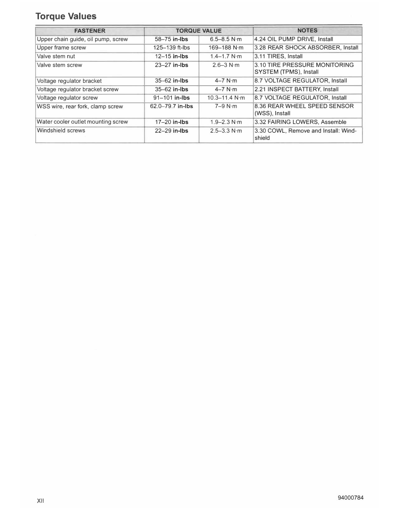
Upper chain guide, oil pump, screw 58-75 in-lbs 6.5-8.5 N·m 4.24 OIL PUMP DRIVE, Install
Upper frame screw 125-139 ft-lbs 169-188 N·m 3.28 REAR SHOCK ABSORBER, Install
Valve stem nut 12-15 in-lbs 1.4-1.7 N·m 3.11 TIRES, Install
Valve stem screw 23-27 in-lbs 2.6-3 N·m 3.10 TIRE PRESSURE MONITORING
SYSTEM (TPMS), Install
Voltage regulator bracket 35-62 in-lbs 4-7 N·m 8.7 VOLTAGE REGULATOR, Install
Voltage regulator bracket screw 35-62 in-lbs 4-7 N·m 2.21 INSPECT BATTERY, Install
Voltage regulator screw 91-101 in-lbs 10.3-11.4 N·m 8.7 VOLTAGE REGULATOR, Install
WSS wire, rear fork, clamp screw 62.0-79.7 in-lbs 7-9 N·m 8.36 REAR WHEEL SPEED SENSOR
(WSS), Install
Water cooler outlet mounting screw 17-20 in-lbs 1.9-2.3 N·m 3.32 FAIRING LOWERS, Assemble
Windshield screws 22-29 in-lbs 2.5-3.3 N·m 3.30 COWL, Remove and Install: Wind-
shield
XII
Index
A C
ABS Module Remove and Install. ..................................... 3-46 Cable Lubrication..............................................................2-12
ABS Module, General.......................................................3-46 Caddy, Front Electrical, Remove and lnstall. .................... 8-58
Adhesive Strips Remove and lnstall ...............................3-124 Caddy, Under Seat...........................................................8-61
Adjust Headlamp..............................................................8-28 Caliper, Front, Remove and lnstall.. ................................. 3-32
Air Filter, Remove and Install............................................2-37 Caliper, Rear, Remove and Install. ................................... 3-38
Aligment, Adjust Wheel.....................................................3-27 Cam Timing......................................................................4-25
Align Headlamp................................................................8-28 Camshaft Covers remove and Install. ............................. .4-21
Alignment, Inspect Wheel.................................................3-27 Camshaft Sprocket Clean and Inspect.............................4-26
Alpha Step..............................................................................I Camshaft Sprocket Remove and lnstall ........................... 4-24
Alternator Remove and lnstall............................................8-8 Camshaft and Phaser Operation......................................4-10
Antenna, Security System, Remove and lnstall. .............. 8-44 Camshafts and Phasers Remove and Install...................4-38
Assemble Topic.......................................................................I Center Stand Remove and lnstall. ..................................3-111
Chain Guards Remove and lnstall....................................3-76
Chain, Drive, Remove and lnstall.......................................5-5
B Chain, Timing, Clean and Inspect.....................................4-26
Chain, Timing, Remove and lnstall...................................4-24
Badges Remove and lnstall............................................3-124 Charcoal Canister Remove and lnstall.............................6-41
Balance Wheels................................................................3-26 Chassis Lubrication..........................................................2-12
Balancer Remove and lnstall............................................4-75 Chassis Specifications........................................................3-5
Balancer, Secondary, Remove and lnstall........................4-31 Clamps, Crimp, Remove and lnstall ................................. 4-16
Battery ........................................................................1-1,2-38 Cleaning.................................................................................11
Battery Tray Remove and lnstall......................................8-63 Clutch Clean and lnspect. ................................................ 5-15
Battery, Clean and lnspect................................................2-39 Clutch Control Clean and Inspect.....................................3-82
Battery, Remove and Install..............................................2-38 Clutch Control Disassemble and Assemble.....................3-84
Battery, Storage................................................................2-39 Clutch Control Remove and Install...................................3-82
Battery, Voltage Test.........................................................2-39 Clutch Disassemble and Assemble..................................5-14
Bearing, Wheel.................................................................2-11 Clutch Remove and lnstall................................................5-12
Bearings, Wheel, Sealed, lnspect... .................................3-19 Clutch Specifications..........................................................5-2
INDEX
Bearings, Wheel, Sealed, Remove and lnstall.................3-19 Clutch, Check and Adjust.................................................2-18
Bleed Brakes, Drain..........................................................3-49 Coil, Ignition, Remove and lnstall.....................................8-16
Bleed Brakes, Fill and Bleed............................................3-49 Compensator, Rear Wheel, Clean and lnspect... .............3-17
Body Control Module Remove and lnstall. ....................... 8-39 Compensator, Rear Wheel, Disassemble and Assemble..3-17
Bracket, Rear License Plate, Remove and lnstall..........3-103 Compensator, Rear Wheel, Remove and lnstall..............3-17
Brake ..................................................................................1-1 Complete Topic.......................................................................I
Brake Caliper, Front, Remove and lnstall.........................3-32 Compression Test.............................................................4-12
Brake Caliper, Rear, Remove and Install..........................3-38 Connecting Rods Clean and lnspect. .............................. .4-78
Brake Fluid Level, Check..................................................2-16 Connecting Rods Disassemble and Assemble.................4-77
Brake Fluid, Drain and Replace........................................2-17 Connecting Rods Remove and lnstall..............................4-77
Brake Line, Front Caliper to ABS Module ......................... 3-42 Connector End Views.......................................................A-23
Brake Line, Front Crossover.............................................3-40 Console Remove and lnstall...............................................6-7
Brake Line, Front Master Cylinder to ABS Module...........3-40 Control Module, Left Hand, Remove and lnstall...............8-19
Brake Line, Rear Caliper to ABS Module.........................3-44 Control Module, Right Hand, Remove and Install............8-22
Brake Line, Rear Master Cylinder to ABS Module...........3-43 Coolant.. .....................................................................1-1,2-23
Brake Lines, lnspect.. .......................................................2-17 Coolant Flow.......................................................................7-3
Brake Master Cylinder, Disassemble and Assemble ........ 3-30 Coolant Hoses Remove and lnstall..................................7-15
Brake Master Cylinder, Front, Clean and Inspect.. ...........3-30 Coolant Level Check...........................................................7-8
Brake Master Cylinder, Front, Remove and lnstall. .......... 3-29 Coolant Manifold Remove and lnstall...............................4-51
Brake Master Cylinder, Rear, Clean and Inspect.............. 3-35 Coolant Overflow Tank Remove and lnstall......................7-14
Brake Master Cylinder, Rear, Disassemble and
Coolant Pump General.....................................................7-13
Assemble..........................................................................3-35
Coolant System, Radiator, Relocate for Service..............7-18
Brake Master Cylinder, Rear, Remove and Install............3-34
Coolant System, Radiator, Remove and lnstall................7-19
Brake Pads, Front, Replace.............................................2-13
Coolant Temperature (ECT), Engine, Sensor, Remove and
Brake Pads, Rear, Replace..............................................2-14
lnstall................................................................................7-17
Brake Pedal, Rear, Remove and lnstall. .........................3-106
Coolant, Drain and Fill System...........................................7-8
Brake Switch, Front, Stoplamp, Remove and lnstall........8-35
Cooling Fan Remove and lnstall. .....................................8-45
Brake Switch, Rear, Stoplamp, Remove and lnstall......... 8-36
Cooling Sysem Specifications............................................7-2
Brake Troubleshooting......................................................2-46
Cooling System Gasket Leak Test. ..................................... 7-6
Brakes, Fill and Bleed.......................................................3-49
Cooling System Leak Detection Dye Test..........................7-6
Brakes, Fluid, Drain..........................................................3-49
Cooling System Operation .................................................. 7-3
Brakes, Inspect.................................................................2-13
Cooling System Pressure Cap Test....................................7-4
Breather Bolt Remove and Install.......................................6-5
Cooling System Pressure Test...........................................7-4
Breather Hoses Remove and Install...................................6-6
Cooling System Troubleshooting........................................7-4
Breather Operation .............................................................4-9
XIII
Index
Cooling Systm Freeze Point Test. ...................................... 7-5 Exhaust System Leak Check............................................2-36
Cornering Lamp Align and Adjust.....................................8-30 Exhaust System Remove and Install................................ 6-37
Cornering Lamp Remove and Install. ............................... 8-30 Exhaust System, General.................................................6-37
Covers, Side, Remove and Install....................................3-52
Cowl Deflectors Remove and lnstall.................................3-88
Cowl Disassemble and Assemble....................................3-86 F
Cowl Remove and Install. .................................................3-86
Cowl Windshield Remove and Install. ..............................3-88 Fairing Remove and Install...............................................3-89
Crankcase Clean and lnspect..........................................4-66 Fan, Cooling, Remove and lnstall....................................8-45
Crankcase Disassemble and Assemble...........................4-66 Fender, Front, Remove and lnstall.................................3-102
Crankcase Oil Nozzles Remove and lnstall.....................4-81 Fob Battery.......................................................................8-43
Crankcase, Left Half, Repair ............................................ 4-71 Footpeg Bracket, Passenger, Remove and lnstall......... 3-107
Crankcase, Right Half, Repair..........................................4-68 Footpeg Bracket, Remove and lnstall. ........................... 3-104
Crankshaft Clean and lnspect..........................................4-78 Footpegs, Passenger, Remove and lnstall..................... 3-107
Crankshaft Disassemble and Assemble ...........................4-77 Footpegs, Rider, Remove and lnstall.............................3-104
Crankshaft Lockout. ......................................................... .4-18 Fork Lock Remove and lnstall..........................................3-73
Crankshaft Position Sensor Remove and Install..............8-46 Fork Stem and Bracket Remove and Install.....................3-69
Crankshaft Remove and lnstall ....................................... .4-77 Fork, Front, Remove and lnstall.......................................3-53
Crimp Clamps Remove and lnstall...................................4-16 Fork, Rear, Clean and lnspect... .......................................3-75
Crossmember, Frame, Remove and lnstall.................... 3-123 Fork, Rear, Disassemble and Assemble .......................... 3-74
Cylinder Head Covers Remove and lnstall.......................4-19 Fork, Rear, Remove and lnstall........................................3-74
Cylinder Heads Clean.......................................................4-34 Fork, Standard Front, Disassemble and Assemble..........3-54
Cylinder Heads Clean and lnspect... ................................4-36 Frame Crossmember Remove and lnstall. ..................... 3-123
Cylinder Heads Disassemble and Assemble ................... .4-35 Freeze Point Test. ............................................................... 7-5
Cylinder Heads Remove and Install.................................4-34 Front Electrical Caddy Remove and Install......................8-58
Cylinder Leakdown Test...................................................4-13 Front Fender Remove and lnstall...................................3-102
Cylinders, Clean and lnspect............................................4-43 Front Fork Remove and Install.........................................3-53
Cylinders, Remove and lnstall..........................................4-43 Front Fork, Standard, Disassemble and Assemble .......... 3-54
Front Wheel Clean and lnspect..........................................3-9
Front Wheel Disassemble and Assemble ...........................3-9
D Front Wheel Remove and lnstall........................................3-8
Fual Injectors Remove and lnstall....................................6-26
Damper Assembly, Steering, Remove and lnstall............ 3-72 Fuel...............................................................................1-1,2-5
Deflectors, Cowl, Remove and lnstall...............................3-88 Fuel Line Remove and lnstall...........................................6-10
Diagnose Smoking Engine or High Oil Consumption....... 4-13 Fuel Line, Drain Line, Remove and lnstall........................6-19
Diagnose Valve Train Noise .............................................4-13 Fuel Line, Purge.................................................................6-9
Disassemble Topics................................................................! Fuel Pressure Test..............................................................6-8
Drive Chain Deflection, Measure......................................2-28 Fuel Pump Remove and lnstall........................................6-17
Drive Chain Remove and Install. ........................................ 5-5 Fuel Pump Specifications...................................................6-2
Drive Chain and Sprockets, lnspect. ................................ 2-27 Fuel Tank Remove and lnstall..........................................6-13
Drive Chain, Adjust...........................................................2-28
Drive Specification ..............................................................5-2
G
E Gasoline ..............................................................................1-1
Gasoline Blends..................................................................2-5
Electrical Specifications......................................................8-3 Gear Position Sensor Remove and lnstall........................8-50
Electrical System Troubleshooting ...................................2-46 General ...................................................................................!
Electronic Control Module Remove and Install.................8-38 General, Cable and Chassis Lubrication ..........................2-12
Emblems, Tank, Remove and lnstall..............................3-124
Engine .................................................................................1-1
Engine Coolant Temperature (ECT) Sensor Remove and H
lnstall. ...............................................................................7-17
Engine Guards Remove and lnstall..................................3-94 Hand Grips Remove and Install........................................3-97
Engine Lubrication..............................................................2-5 Handlebar Remove and Install.........................................3-99
Handling Troubleshooting .................................................2-46
Engine Oil Flow .................................................................. .4-6
Harness, Engine, Remove and lnstall..............................8-66
Engine Oil and Filter, Change .............................................2-7
Harness, Main, Remove and lnstall..................................8-70
Engine Oil and Filter, Check...............................................2-7
Headlamp Adjustment......................................................8-28
Engine Remove and Install...............................................4-60
Headlamp Alignment........................................................8-28
Engine Service Wear Limits ............................................... .4-4
Headlamp Remove and Install. ........................................ 8-28
Engine Specifications .........................................................4-3
Heads, Cylinder, Clean .....................................................4-34
Engine Troubleshooting....................................................2-44
Heads, Cylinder, Clean and Inspect.................................4-36
Engine Wire Harness Remove and Install........................8-66
Heads, Cylinder, Disassemble and Assemble ..................4-35
Enhanced Chassis Control. ..............................................3-28
XIV
Index
Heads, Cylinder, Remove and lnstall...............................4-34 Mirrors Remove and lnstall.............................................3-101
Heated Oxygen Sensors Remove and Install................... 6-33 Motorcycle Storage .......................................................... 2-43
Horn Remove and lnstall..................................................8-27 Mufflers Remove and lnstall. ............................................ 6-35
Hose, Overflow, Remove and lnstall................................7-15
Hydraulic Fluid ....................................................................1-1
N
Numeric Step ..........................................................................I
IMU Remove and lnstall...................................................8-55
lcons .......................................................................................l 0
Ignition Coil Remove and lnstall. ...................................... 8-16
Induction Module Remove and lnstall.............................. 6-28 Oil .......................................................................................1-1
Injectors, Fuel, Remove and lnstall..................................6-26 Oil Consumption, High, Diagnose....................................4-13
Inspect Brakes..................................................................2-13 Oil Cooler and Downtube Remove and Install..................4-17
lnstake Air Temperature Sensor Remove and lnstall....... 6-21 Oil Flow, Engine ..................................................................4-6
Install Topics ...........................................................................I Oil Leak Check, Front Fork ...............................................3-53
Instrument Module Remove and lnstall............................8-24 Oil Nozzles, Crankcase, Remove and lnstall...................4-81
Intake Leak Test................................................................6-32 Oil Pressure Check ...........................................................4-11
Intake Manifold Remove and lnstall.................................6-30 Oil Pressure Operation .....................................................4-11
Isolator, Rear Sprocket, Inspect... .................................... 2-30 Oil Pressure Switch Remove and lnstall.......................... 8-26
Oil Pump Operation ............................................................4-8
Oil Pump Operation, General.............................................4-8
J Oil Pump Remove and Install...........................................4-59
Oil and Filter, Engine, Change ............................................2-7
Jiffy Stand Disassemble and Assemble..........................3-109 Oil and Filter, Engine, Check ..............................................2-7
Jiffy Stand Remove and lnstall.......................................3-109 Order of Operation ..................................................................I
Jiffy Stand Sensor Remove and lnstall.............................8-57 Overflow Hose Remove and lnstall. ................................. 7-15
Overflow Tank, Coolant, Remove and lnstall. ................... 7-14
Oxygen Sensors, Heated, Remove and lnstall ................. 6-33
K
Knock Sensor Remove and Install. .................................. 8-49 p
Phaser Solenoids Remove and Install ..............................4-22
L Phaser and Camshaft Operation ......................................4-10
Phasers and Camshafts Remove and lnstall...................4-38
Lamp, Cornering, Align and Adjust...................................8-30 Piston Ring Gap Check ....................................................4-47
Lamp, Cornering, Remove and lnstall..............................8-30 Pistons Clean and Inspect... ............................................ .4-46
Layout.....................................................................................! Pistons Disassemble and Assemble................................ 4-46
Leak Test, Intake ...............................................................6-32 Pistons Remove and Install..............................................4-45
License Plate Bracket, Rear, Remove and lnstall..........3-103 Plugs and Oil Fittings........................................................4-73
License Plate Lamp Remove and Install..........................8-37 Power Disconnect...............................................................8-4
Lock, Fork, Remove and lnstall........................................3-73 Power Disconnect, Main Fuse ............................................8-4
Lockout, Crankshaft ..........................................................4-18 Prepare Topic..........................................................................1
Loctite ...................................................................................III Pressure Cap, Cooling System, Test. ................................. 7-4
Lubrication Points ............................................................ 2-12 Pressure Test, Cooling System ..........................................7-4
Lubrication System Troubleshooting................................2-45 Primary Cover Disassemble and Assemble .....................4-50
Lubrication, Engine .............................................................2-5 Primary Cover Remove and Install ...................................4-49
Pump, Oil, Operation ..........................................................4-8
Purge Solenoid Remove and Install.................................6-40
M
Purge, Fuel Vapor Vent Line, Remove and lnstall............6-42
Main Wire Harness Remove and lnstall. .......................... 8-70
Maintenance .......................................................................2-2
R
Maintenance Schedule .......................................................2-3
Manual ..................................................................................1,I Radiator Remove and lnstall............................................7-19
Master Cylinder, Front Brake, Clean and lnspect.............3-30 Radiator, Clean .................................................................2-23
Master Cylinder, Front Brake, Disassemble and Radiator, Relocate for Service..........................................7-18
Assemble ..........................................................................3-30 Rear Fork Clean and lnspect. ...........................................3-75
Master Cylinder, Front Brake, Remove and lnstall........... 3-29
Rear Fork Disassemble and Assemble............................3-74
Master Cylinder, Rear Brake, Clean and Inspect............. 3-35
Rear Fork Remove and lnstall..........................................3-74
Master Cylinder, Rear Brake, Disassemble and
Rear License Plate Bracket Remove and Install............3-103
Assemble ..........................................................................3-35
Rear Shock Absorber Clean and lnspect.........................3-79
Master Cylinder, Rear Brake, Remove and Install............3-34
Rear Shock Absorber Remove and lnstall ....................... 3-78
Medallions Remove and lnstall.......................................3-124
Rear Wheel Clean and lnspect.........................................3-12
xv
Index
Rear Wheel Disassemble and Assemble.........................3-12 Tail Section Remove and lnstall .....................................3-114
Rear Wheel Remove and lnstall.......................................3-11 Tank Emblems Remove and lnstall................................3-124
Reflex Defensive Rider System ........................................3-28 Temperature Manifold Absolute Pressure Sensor Remove and
Regulator, Voltage, Remove and Install...........................8-13 lnstall................................................................................6-22
Remove Topic.........................................................................I Temperature Sensor, Air Intake, Remove and lnstall....... 6-21
Ring Gap, Pistons, Check.................................................4-47 Test, Compression ............................................................4-12
Runout, Checking Wheel..................................................3-16 Test, Cylinder Leakdown ..................................................4-13
Runout, Tire, Check..........................................................3-25 Test, Fuel Pressure.............................................................6-8
Test, Intake Leak ...............................................................6-32
Thermostat Housing Remove and lnstall.........................7-11
s Throttle Control Actuator General.....................................6-25
Timing Chain Clean and Inspect.......................................4-26
Safety..................................................................................1-1 Timing Chain Remove and Install.....................................4-24
Schedule, Maintenance......................................................2-3 Timing, Cam .....................................................................4-25
Seat Remove and Install................................................3-113 Tire Pressure Monitoring System (TPMS)........................ 3-21
Secure Motorcycle for Service ............................................2-2 Tire Runout, Check...........................................................3-25
Security System Activation...............................................8-40 Tires..................................................................................3-24
Security System Antenna Remove and Install.................8-44 Tires, Clean, Inspect and Repair......................................3-24
Security System Maintenance..........................................8-43 Tires, General.....................................................................2-9
Security System, Changing the PIN.................................8-41 Tires, Inspect......................................................................2-9
Service Mode....................................................................8-43 Tires, Remove and lnstall.................................................3-23
Service Wear Limits, Engine...............................................4-4 Tires, Replace............................................................2-9,2-10
Servicing a New Motorcycle...............................................2-2 Tool.......................................................................................1II
Shifter Shaft Disassemble and Assemble ........................5-10 Trademarks .......................................................................III,III
Shifter Shaft Remove and lnstall. .......................................5-8 Transmission Disassemble and Assemble.......................5-20
Shock Absorber, Rear, Clean and lnspect... ..................... 3-79 Transmission Drum and Forks Remove and lnstall .......... 5-19
Shock Absorber, Rear, Remove and lnstall......................3-78 Transmission Operation......................................................5-3
Shop Practices ...................................................................1I,III Transmission Remove and Install.....................................5-20
Side Covers Remove and lnstall ......................................3-52 Transmission Specifications.........................................5-2,5-2
Skid Plate Remove and Install..........................................3-92 Transmission Troubleshooting..........................................2-46
Smoking Engine, Diagnose..............................................4-13 Transport Mode................................................................8-43
Soleniod, Purge, Remove and lnstall...............................6-40 Troubleshooting Tables.....................................................4-14
Spark Plug Cables Remove and lnstall............................8-15 Troubleshooting, Brakes...................................................2-46
Spark Plugs, Install...........................................................2-41 Troubleshooting, Electrical System ..................................2-46
Spark Plugs, Remove and lnstall.....................................2-41 Troubleshooting, Engine...................................................2-44
Special Tools.........................................................................111 Troubleshooting, General.................................................2-44
Specifications, Chassis.......................................................3-5 Troubleshooting, Handling................................................2-46
Specifications, Electrical.....................................................8-3 Troubleshooting, Lubrication System ...............................2-45
Specifications, Fuel Pump ..................................................6-2 Troubleshooting, Transmission.........................................2-46
Spoke, Wheel Lacing........................................................3-14 Turn Signal Lamps, Front, Remove and lnstall................8-32
Spokes, Wheel..................................................................2-11 Turn Signal Lamps, Rear, Remove and Install.................8-33
Sprocket Isolator, Rear, lnspect........................................2-30 Twist Grip Sensor Remove and Install.....................6-24,8-54
Sprocket, Camshaft Clean and Inspect............................4-26
Sprocket, Camshaft, Remove and Install.........................4-24
Stand, Center, Remove and lnstall.................................3-111 u
Stand, Jiffy, Remove and lnstall.....................................3-109
Starter Gear Remove and Install......................................4-56 Under Seat Caddy............................................................8-61
Starter Remove and lnstall.................................................8-5 Using the Manual. ...................................................................1
Starter Solenoid Remove and lnstall..................................8-7
Steering Damper Assembly Remove and lnstall. ............. 3-72
Steering Head Bearings, Check and Adjust... ..................2-21 V
Steering Head Bearings, Lubricate ...................................2-22
Steering Head Remove and Install. ..................................3-69 VVT Harness Remove and lnstall....................................8-64
Stoplamp Switch, Front, Remove and lnstall. ................... 8-35 Valve Train Noise, Diagnose............................................4-13
Stoplamp Switch, Rear, Remove and lnstall....................8-36 Vehicle Identification Number (VIN)....................................3-6
Storage, Place Motorcycle in............................................2-43 Voltage Regulator Remove and lnstall.............................8-13
Storage, Remove Motorcycle from ...................................2-43
Symbols ..................................................................................!
w
Wear Limits, Service, Engine.............................................. 4-4
T
Wheel Alignment, Adjust.. .................................................3-27
Tail Lamp Remove and Install..........................................8-34 Wheel Alignment, Inspect.................................................3-27
Tail Section Disassemble and Assemble........................ 3-114 Wheel Bearings................................................................2-11
XVI
Index
Wheel Bearings, Sealed, lnspect.....................................3-19
Wheel Bearings, Sealed, Remove and lnstall..................3-19
Wheel Compensator, Rear, Clean and lnspect................3-17
Wheel Compensator, Rear, Disassemble and Assemble ..3-17
Wheel Compensator, Rear, Remove and lnstall...............3-17
Wheel Lacing ....................................................................3-14
Wheel Speed Sensor, Front, Remove and lnstall.............8-51
Wheel Speed Sensor, Rear, Remove and lnstall. ............8-52
Wheel Spokes ...................................................................2-11
Wheel, Front, Clean and lnspect. .......................................3-9
Wheel, Front, Disassemble and Assemble.........................3-9
Wheel, Front, Remove and lnstall......................................3-8
Wheel, Rear, Clean and lnspect.......................................3-12
Wheel, Rear, Disassemble and Assemble.......................3-12
Wheel, Rear, Remove and lnstall .....................................3-11
Wheels, Balance...............................................................3-26
Wheels, Checking Wheel Runout.....................................3-16
Wheels, Checking and Truing, General............................3-16
Wheels, General.................................................................2-9
Windshield Remove and lnstall........................................3-88
Wiring Diagrams .................................................................A-2
XVII
NOTES