🏍️ PAN AMERICA SERWIS

3.14 Front Brake Master Cylinder

Fragment manuala — str. 107–109

📋 Tekst do skopiowania (OCR/wyszukiwanie)
FRONT BRAKE MASTER CYLINDER                                                                                               3.14
PREPARE                                                                C.   Install screws (3). Tighten.
                                                                            Torque: 62-80 in-lbs (7-9 N·m) Brake, front master
1.   Remove main fuse.         See POWER          DISCONNECT                cylinder mounting screw
     (Page 8-4).
                                                                  2.   If disconnected: Connect front stoplamp switch.
2.   Remove right hand guard. See HANDLEBAR WIND
     DEFLECTORS (Page 3-96).                                                                 NOTICE

                                                                  Avoid leakage. Be sure gaskets, banjo bolt(s), brake line
3.   If replacing master cylinder: Drain brake fluid from front   and master cylinder bore are clean and undamaged before
     brake system. See BLEED BRAKES (Page 3-49).                  assembly. (00322a)

4.   If replacing master cylinder: Remove front stop lamp
                                                                  3.   If replacing master cylinder: Attach brake line.
     switch. See FRONT STOPLAMP SWITCH (Page 8-35).

REMOVE                                                                 a.   Attach brake line (4) with banjo bolt (5), and new
                                                                            gasket washers (6).

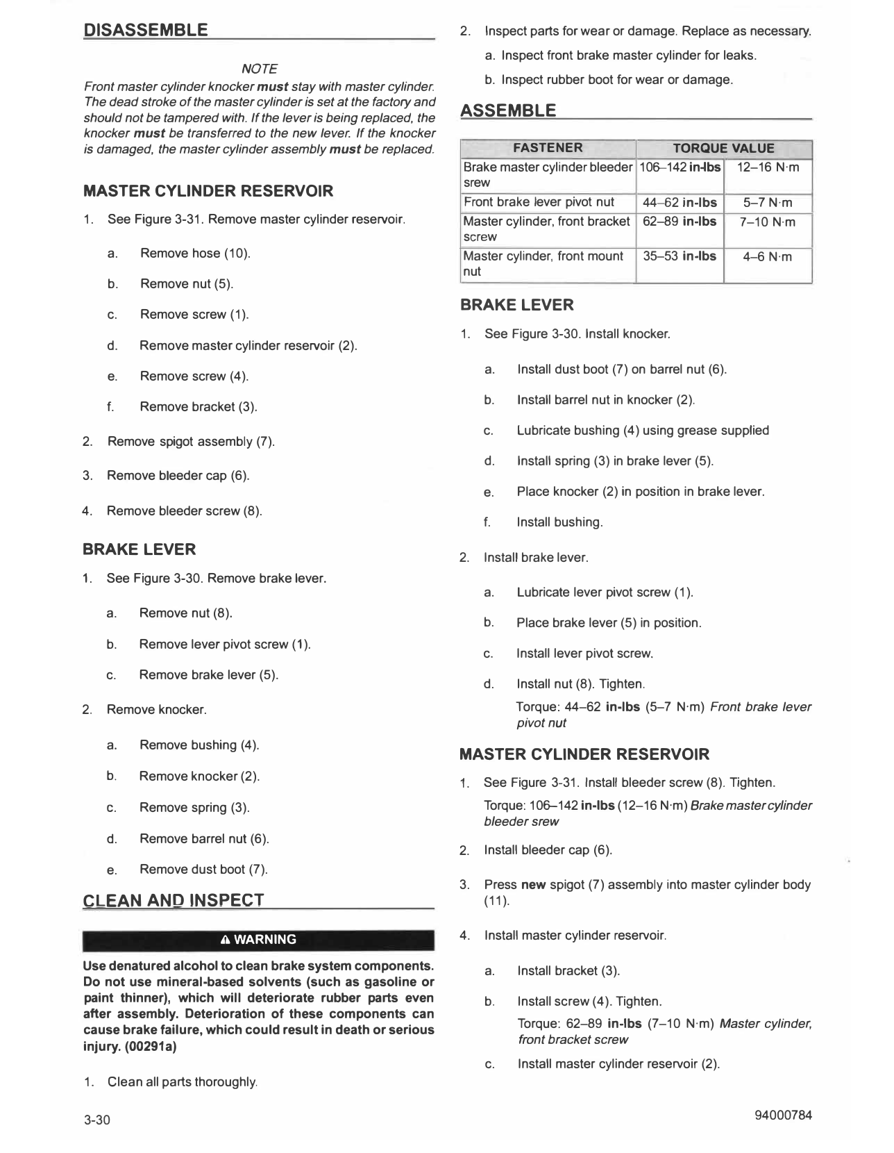
                            NOTICE                                     b.   See Figure 3-29. Position brake line as shown.

DOT 4 brake fluid will damage painted and body panel                   c.   Tighten banjo bolt.
surfaces it comes in contact with. Always use caution and
protect surfaces from spills whenever brake work is                         Torque: 17-19ft-lbs (23-26 N·m) Brake, front master
performed. Failure to comply can result in cosmetic                         cylinder banjo bolt
damage. (00239c)

• If DOT 4 brake fluid contacts painted               surfaces,
  IMMEDIATELY flush area with clear water.

1.                    NOTE
See Figure 3-29. Record position of brake line before
removing.

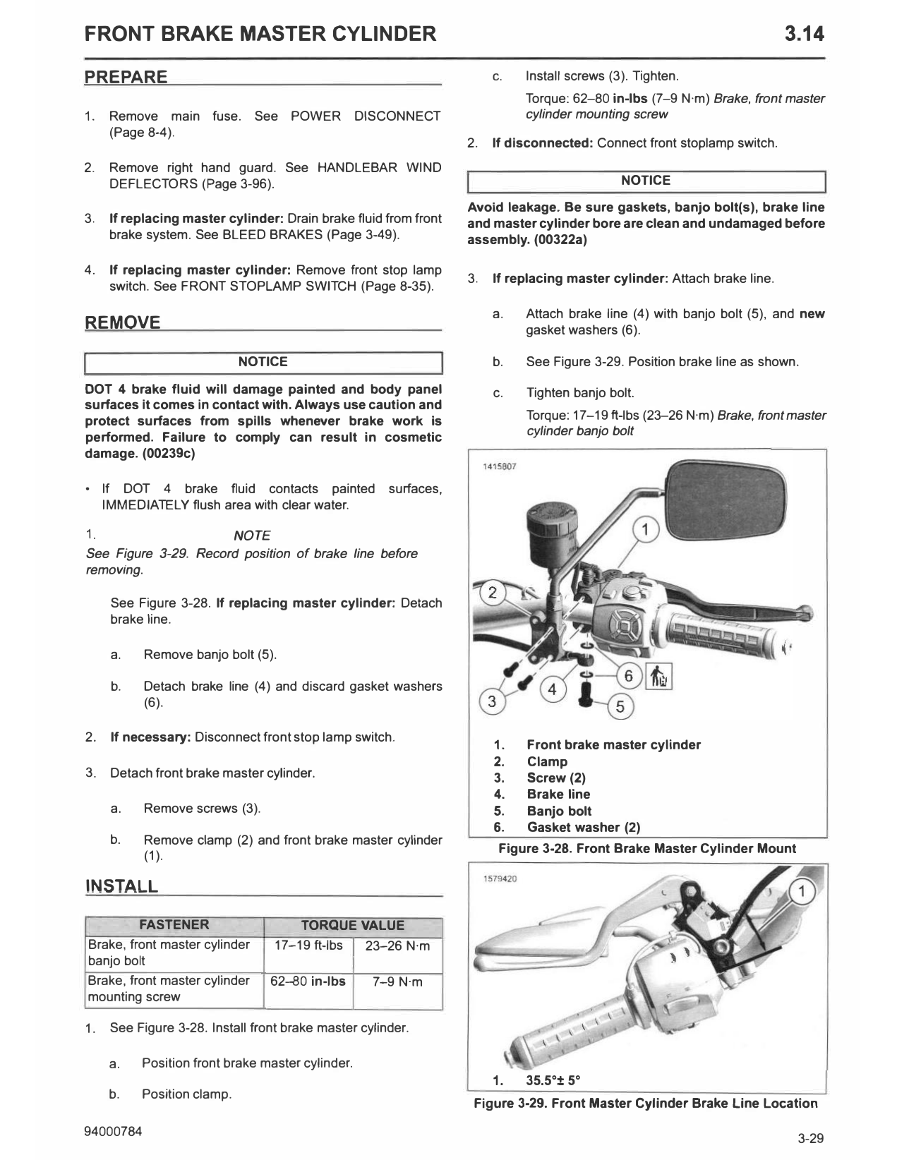
     See Figure 3-28. If replacing master cylinder: Detach
     brake line.

     a.    Remove banjo bolt (5).

     b.    Detach brake line (4) and discard gasket washers
           (6).

2.   If necessary: Disconnect front stop lamp switch.
                                                                       1.   Front brake master cylinder
                                                                       2.   Clamp
3.   Detach front brake master cylinder.                               3.   Screw (2)
                                                                       4.   Brake line
     a.    Remove screws (3).                                          5.   Banjo bolt
                                                                       6.   Gasket washer (2)
     b.    Remove clamp (2) and front brake master cylinder
                                                                        Figure 3-28. Front Brake Master Cylinder Mount
           (1).

INSTALL

         FASTENER                     TORQUE VALUE
Brake, front master cylinder      17-19 ft-lbs 23-26 N·m
banjo bolt
Brake, front master cylinder     62--80 in-lbs      7-9 N·m
mounting screw

1.   See Figure 3-28. Install front brake master cylinder.

     a.   Position front brake master cylinder.
                                                                       1.   35.5 °± 5 °
     b.   Position clamp.
                                                                   Figure 3-29. Front Master Cylinder Brake Line Location

DISASSEMBLE                                                        2.   Inspect parts for wear or damage. Replace as necessary.
                                                                        a. Inspect front brake master cylinder for leaks.
                           NOTE
                                                                        b. Inspect rubber boot for wear or damage.
Front master cylinder knocker must stay with master cylinder
The dead stroke of the master cylinder is set at the factory and
should not be tampered with. If the lever is being replaced, the   ASSEMBLE
knocker must be transferred to the new lever. If the knocker
is damaged, the master cylinder assembly must be replaced.                  FASTENER                   TORQUE VALUE
                                                                   Brake master cylinder bleeder 106--142 in-lbs 12-16 N·m
                                                                   srew
MASTER CYLINDER RESERVOIR
                                                                   Front brake lever pivot nut    44--62 in-lbs   5-7 N·m
1.   See Figure 3-31. Remove master cylinder reservoir.            Master cylinder, front bracket 62-89 in-lbs   7-10 N·m
                                                                   screw
     a.   Remove hose (10).                                        Master cylinder, front mount   35-53 in-lbs    4-6 N·m
                                                                   nut
     b.   Remove nut (5).
                                                                   BRAKE LEVER
     c.   Remove screw (1).
                                                                   1.   See Figure 3-30. Install knocker.
     d.   Remove master cylinder reservoir (2).
                                                                        a.    Install dust boot (7) on barrel nut (6).
     e.   Remove screw (4).
                                                                        b.    Install barrel nut in knocker (2).
     f.   Remove bracket (3).
                                                                        c.    Lubricate bushing (4) using grease supplied
2.   Remove spigot assembly (7).
                                                                        d.    Install spring (3) in brake lever (5).
3.   Remove bleeder cap (6).
                                                                        e.    Place knocker (2) in position in brake lever.
4.   Remove bleeder screw (8).
                                                                        f.    Install bushing.

BRAKE LEVER                                                        2.   Install brake lever.
1.   See Figure 3-30. Remove brake lever.
                                                                        a.    Lubricate lever pivot screw (1).
     a.   Remove nut (8).
                                                                        b.    Place brake lever (5) in position.
     b.   Remove lever pivot screw (1).
                                                                        c.    Install lever pivot screw.
     c.   Remove brake lever (5).
                                                                        d.    Install nut (8). Tighten.
2.   Remove knocker.                                                          Torque: 44-62 in-lbs (5-7 N·m) Front brake lever
                                                                              pivot nut
     a.   Remove bushing (4).
                                                                   MASTER CYLINDER RESERVOIR
     b.   Remove knocker (2).
                                                                   1.   See Figure 3-31. Install bleeder screw (8). Tighten.
     C.   Remove spring (3).                                            Torque: 106--142 in-lbs (12-16 N·m) Brake master cylinder
                                                                        bleeder srew
     d.   Remove barrel nut (6).
                                                                   2.   Install bleeder cap (6).
     e.   Remove dust boot (7).
                                                                   3.   Press new spigot (7) assembly into master cylinder body
CLEAN AND INSPECT                                                       (11).

                         A WARNING                                 4.   Install master cylinder reservoir.

Use denatured alcohol to clean brake system components.                 a.    Install bracket (3).
Do not use mineral-based solvents (such as gasoline or
paint thinner), which will deteriorate rubber parts even                b.    Install screw (4). Tighten.
after assembly. Deterioration of these components can
                                                                              Torque: 62-89 in-lbs (7-10 N·m) Master cylinder,
cause brake failure, which could result in death or serious
                                                                              front bracket screw
injury. (00291a)
                                                                        c.    Install master cylinder reservoir (2).
1.   Clean all parts thoroughly.

3-30                                                                                                                     94000784
   d.         Install screw (1).
                                                                     1473891

   e.         Install nut (5). Tighten.
              Torque: 35-53 in-lbs (4-6 N·m) Master cylinder,
              front mount nut                                                       Gr
   f.         Install hose (10).

   g.         Install spring clamps (9).

 14738
         72
              � I ?I

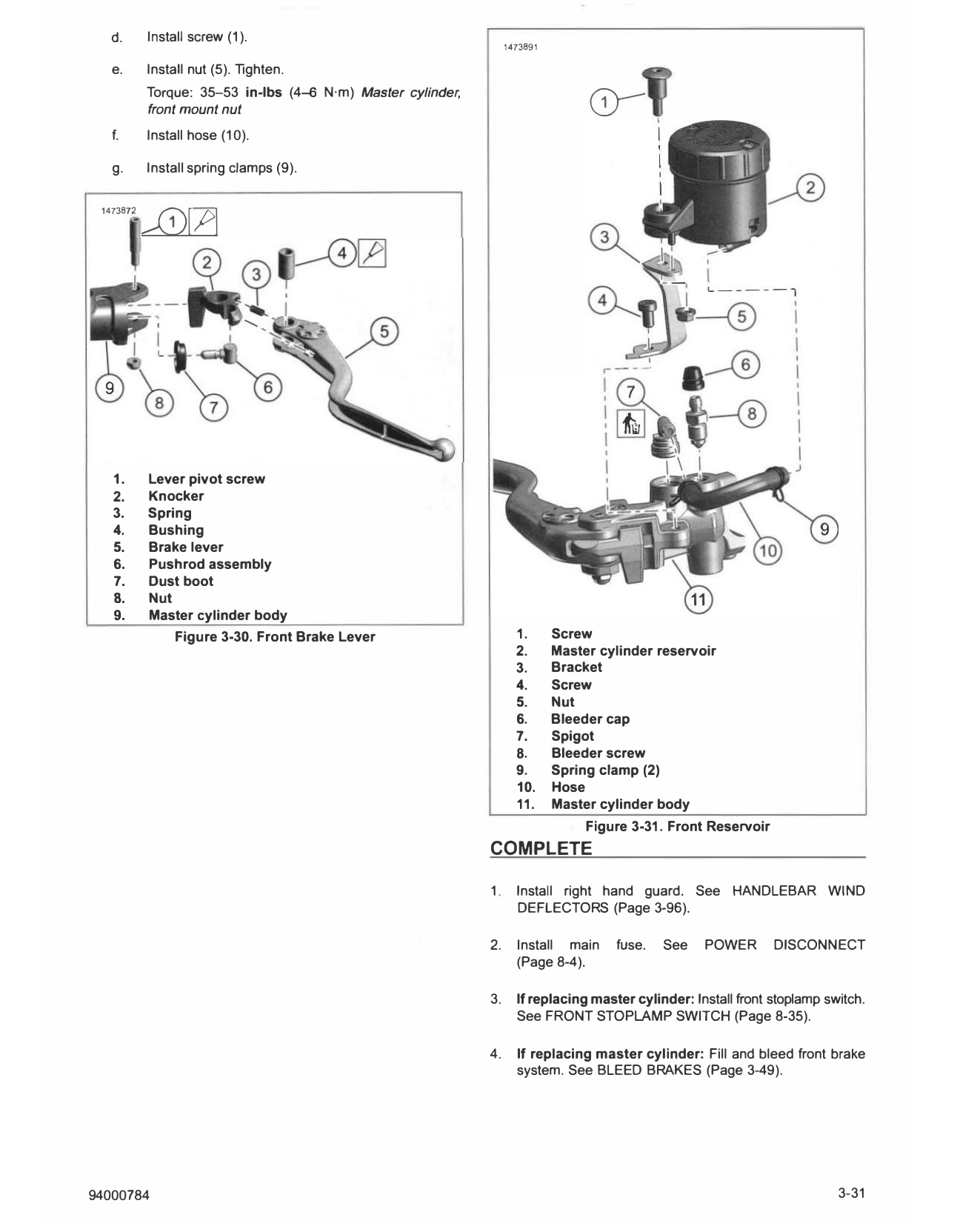
   1.         Lever pivot screw
   2.         Knocker
   3.         Spring
   4.         Bushing
   5.         Brake lever
   6.         Pushrod assembly
   7.         Dust boot
   8.         Nut
   9.         Master cylinder body
                   Figure 3-30. Front Brake Lever                      1.      Screw
                                                                       2.      Master cylinder reservoir
                                                                       3.      Bracket
                                                                       4.      Screw
                                                                       5.      Nut
                                                                       6.      Bleeder cap
                                                                       7.      Spigot
                                                                       8.      Bleeder screw
                                                                       9.      Spring clamp (2)
                                                                       10.     Hose
                                                                       11.     Master cylinder body
                                                                                    Figure 3-31. Front Reservoir
                                                                COMPLETE

                                                                1.     Install right hand guard. See HANDLEBAR WIND
                                                                       DEFLECTORS (Page 3-96).

                                                                2.     Install main     fuse.   See    POWER       DISCONNECT
                                                                       (Page 8-4).

                                                                3.     If replacing master cylinder: Install front stoplamp switch.
                                                                       See FRONT STOPLAMP SWITCH (Page 8-35).

                                                                4.     If replacing master cylinder: Fill and bleed front brake
                                                                       system. See BLEED BRAKES (Page 3-49).

94000784                                                                                                                      3-31