2.12 Adjust And Lubricate Steering Head Bearings
Fragment manuala — str. 51–52
📋 Tekst do skopiowania (OCR/wyszukiwanie)
ADJUST AND LUBRICATE STEERING HEAD BEARINGS 2.12
PREPARE 1. See Figure 2-19. Loosen upper fork bracket pinch screws
(1).
1. Move forks from stop to stop to check for smooth operation.
Rough operation indicates damaged bearings. See 2. See Figure 2-20. Loosen fork stem pinch screw (3).
STEERING HE AD (Page 3-69)
3. Remove P clamp screw (2).
2. Remove fairing. See FAIRING (Page 3-89).
4. Adjust fork stem screw (1).
3. If equipped: Remove steering damper fastener. See
STEERING DAMPER ASSEMBLY (Page 3-72). a. If pull force dimension is more than the maximum,
loosen the fork stem screw.
CHECK AND ADJUST b. If pull force dimension is less than the minimum,
tighten the fork stem screw.
FASTENER TORQUE VALUE
Brake line P clamp screw, up- 62-80 in-lbs 7-9 N·m 5. Tighten fork stem pinch screw.
per fork bracket
Torque: 15-18 ft-lbs (20-24 N·m) Fork stem pinch screw
Fork bracket, upper pinch 15-18 ft-lbs 20.4-25 N·m
screws 6. Install P clamp screw. Tighten.
Fork stem pinch screw 15-18 ft-lbs 20-24 N·m
Torque: 62-80 in-lbs (7-9 N·m) Brake line P clamp screw,
upper fork bracket
Measure:
7. See Figure 2-20. Tighten upper fork bracket pinch screws.
1. H ave a helper position motorcycle vertical with steering
straight. Torque: 15-18 ft-lbs (20.4-25 N·m) Fork bracket, upper
pinch screws
2. Measure fork angle.
8. Repeat measure and adjust as needed.
a. Measure fork angle on a vertical bike (steering
straight). Table 2-11. Pull Force Specifications
MODEL MINIMUM MAXIMUM
b. Raise motorcycle. See Secure the Motorcycle for 3 6
Service (Page 2-2)
c. Make sure the fork angle is the same lifted as it was
on the ground.
d. Use a suitable cell phone app or angle finder
accurate within a degree or two.
3. Perform test.
a. Move handlebars from left to right steering stops
three times, ending at full left steering stop.
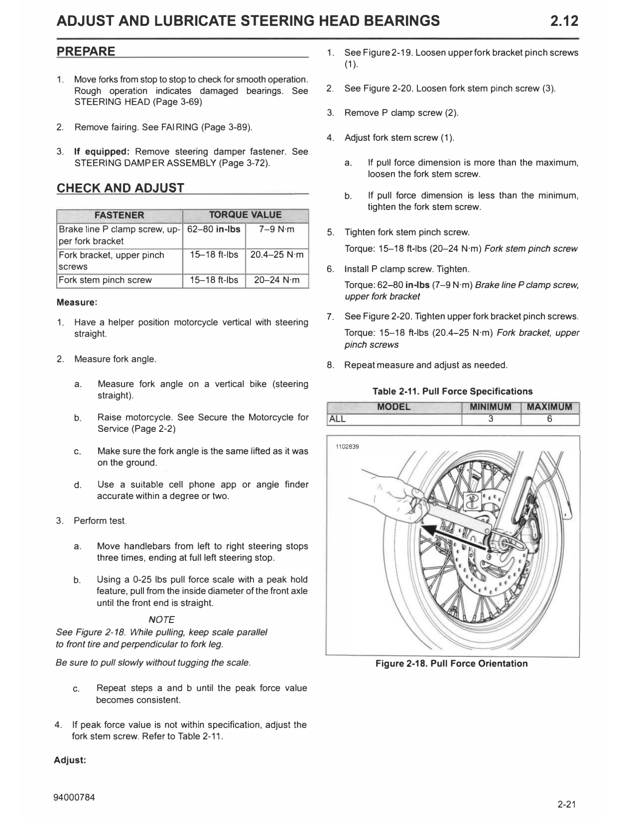
b. Using a 0-25 lbs pull force scale with a peak hold
feature, pull from the inside diameter of the front axle
until the front end is straight.
NOTE
See Figure 2-18. While pulling, keep scale parallel
to front tire and perpendicular to fork leg.
Be sure to pull slowly without tugging the scale. Figure 2-18. Pull Force Orientation
c. Repeat steps a and b until the peak force value
becomes consistent.
4. If peak force value is not within specification, adjust the
fork stem screw. Refer to Table 2-11.
Adjust:
LUBRICATE
CONSUMABLE PART NUMBER
SPECIAL 99857-97A
PURPOSE
GREASE
Disassemble the steering head assembly and lubricate the
tapered roller bearings with SPECIAL PURPOSE GREASE
(99857-97A). See STEERING HEAD (Page 3-69).
COMPLETE
1. If equipped and steering damper fastener was removed,
install fastener. Tighten to specification. See STEERING
DAMPER ASSEMBLY (Page 3-72).
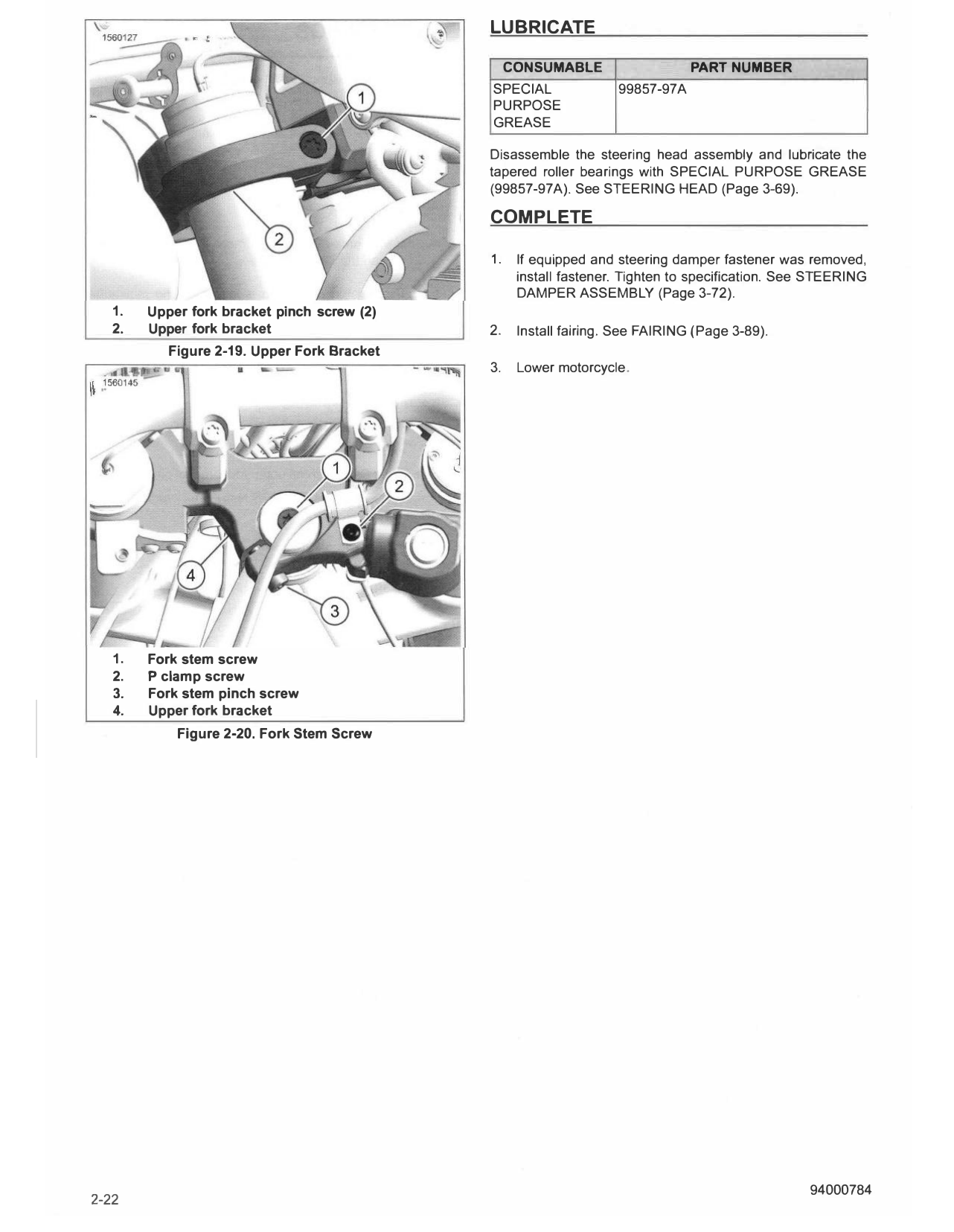
1. Upper fork bracket pinch screw (2)
2. Upper fork bracket 2. Install fairing. See FAIRING (Page 3-89).
Figure 2-19. Upper Fork Bracket
3. Lower motorcycle.
1. Fork stem screw
2. P clamp screw
3. Fork stem pinch screw
4. Upper fork bracket
Figure 2-20. Fork Stem Screw